
Supporting structure of low cast-in-place capping beam and construction method thereof

A supporting structure and cover beam technology, which is applied to bridges, bridge parts, bridge construction, etc., can solve the problems of large influence of structures under the soil, large amount of earthwork excavation, disturbance of undisturbed soil, etc., to achieve small disturbance and occupy space Less, easy to remove the effect

Pending Publication Date: 2019-11-08
广州市第三市政工程有限公司
View PDF0 Cites 0 Cited by
  • Summary
  • Abstract
  • Description
  • Claims
  • Application Information

AI Technical Summary

Problems solved by technology

[0002] At present, the conventional cast-in-place cover beam needs to be built on the cast-in-place cover beam support, and the cast-in-place cover beam support needs to occupy a large construction space, which requires a large amount of earthwork excavation, disturbs the undisturbed soil, and affects the structure below the soil. Greater impact

Method used


Image

  • Supporting structure of low cast-in-place capping beam and construction method thereof

Examples


Embodiment Construction

[0025] The following will clearly and completely describe the technical solutions in the embodiments of the present invention with reference to the accompanying drawings in the embodiments of the present invention. Obviously, the described embodiments are only some, not all, embodiments of the present invention. Based on the embodiments of the present invention, all other embodiments obtained by persons of ordinary skill in the art without creative efforts fall within the protection scope of the present invention.

[0026] In the description of the present invention, it should be noted that the terms "center", "longitudinal", "transverse", "upper", "lower", "front", "rear", "left", "right", " The orientations or positional relationships indicated by "vertical", "horizontal", "top", "bottom", "inner", "outer", etc. are based on the orientation or positional relationships shown in the drawings, and are only for the convenience of describing the present invention and simplifying ...


PUM


Abstract

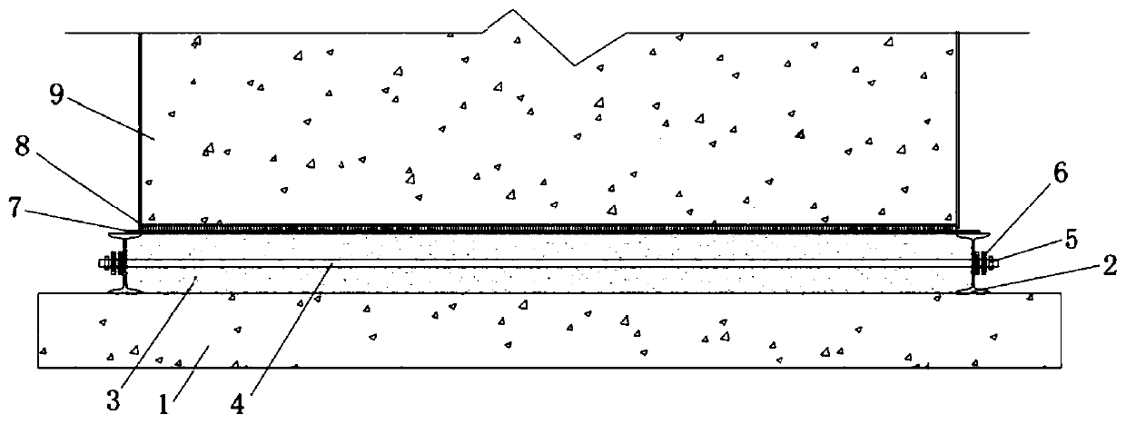
The invention relates to a supporting structure of a low cast-in-place capping beam and a construction method thereof. The supporting structure comprises a concrete cushion ply, a sand box, a plasticfilm and a bottom template arranged successively from bottom to top. The sand box comprises a frame, a split bolt and fine sand filler. The frame comprises two longitudinal frame strips and two transverse frame strips, a plurality of through holes are separately formed in corresponding positions of the two longitudinal frame strips, the split bolt comprises a split screw provided with threaded parts at two ends and two nuts, the split screw penetrates the frame and the thread parts of the split screw stretch out of the longitudinal frame strips through the through holes, the nuts are arrangedon the thread parts in a sleeving manner and are tightened till the nuts are compressed to the longitudinal frame strips, an inner cavity of the frame is fully filled with the fine sand filler, the top surface of the fine sand filler is aligned with the top surface of the frame, the plastic film covers the top surface of the sand box, the bottom template is arranged on the plastic film, and the capping beam is poured to the bottom template. According to the invention, the low cast-in-place capping beam can be constructed in a narrow space, disturbance to a soil body below is small, and the supporting structure is simple to construct and detach without affecting the safety of the structure below the soil body.

Description

technical field [0001] The invention relates to the field of bridge construction, in particular to a support structure of a low cast-in-place cap beam and a construction method thereof. Background technique [0002] At present, the conventional cast-in-place cover beam needs to be built on the cast-in-place cover beam support, and the cast-in-place cover beam support needs to occupy a large construction space, which requires a large amount of earthwork excavation, disturbs the undisturbed soil, and affects the structure below the soil. Greater impact. Contents of the invention [0003] The problem to be solved by the present invention is to provide a support structure of a low cast-in-place cover beam and its construction method, which can construct a low cast-in-place cover beam in a narrow space, without being affected by the construction space, and has no impact on the soil below. The disturbance is small, the construction and disassembly of the support structure are s...

Claims


Application Information

Patent Timeline
Patent Type & Authority Applications(China)
IPC IPC(8): E01D19/00E01D19/02E01D21/00
CPCE01D19/00E01D19/02E01D21/00
Inventor 郭一贤吴应军何铭陈建宁颜苓陈衡
Owner 广州市第三市政工程有限公司
Learn More