Engine brake device

A technology of engine braking and control cavity, which is applied in the direction of engine control, engine components, machines/engines, etc., can solve the problems of poor reliability and durability, complex engine braking structure, etc., and achieve compact space, stable and efficient braking work , Simple and stable structure

Pending Publication Date: 2019-11-08
ZHEJIANG LIMING INTELLIGENT MFG CO LTD
View PDF2 Cites 8 Cited by
  • Summary
  • Abstract
  • Description
  • Claims
  • Application Information

AI Technical Summary

Problems solved by technology

[0008] In order to overcome the deficiencies of the background technology, the present invention provides an engine braking device

Method used


Image

  • Engine brake device
  • Engine brake device
  • Engine brake device

Examples


Embodiment Construction

[0042]Embodiments of the present invention will be further described below in conjunction with accompanying drawings:

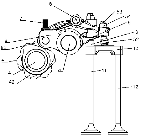
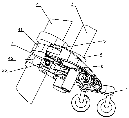
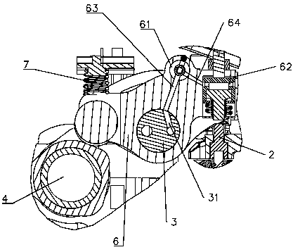
[0043] As shown in the figure, an engine braking device includes an exhaust valve 1, a sliding pin 2, a rocker shaft 3, a camshaft 4, an exhaust rocker 5, an auxiliary rocker 6, an elastic element 7, a control mechanism 8, Executive body9.

[0044] The exhaust valve 1 includes a first exhaust valve 11, a second exhaust valve 12, and a valve bridge 13 horizontally arranged on the first exhaust valve 11 and the second exhaust valve 12, the first exhaust valve 11 and the second exhaust valve 12 The second exhaust valves 12 all adopt mushroom valves, which are used to control the flow of gas between the combustion chamber in the engine and the intake and exhaust manifolds.

[0045] The sliding pin 2 is arranged in the valve bridge 13, one end of which is in contact with the first exhaust valve 11, and the other end passes through the valve bridge 13, and when th...


PUM


Abstract

The invention relates to an engine brake device. A control mechanism is disposed in a control cavity, and comprises a one-way control valve, a first spring and a retaining ring; the one-way control valve has a first position that is pushed by the oil to unidirectionally close a second oil passage, and a second position that is pushed by the first spring to open the second oil passage; an actuatoris disposed in an execution cavity, and comprises an adjusting bolt, a housing, a cover, a second spring, an execution plunger, and a third spring; the execution plunger has a third position that maintains a certain brake clearance with a sliding pin and a fourth position that can contact the sliding pin and drive the sliding pin for braking. The engine brake device has the advantages of simple and stable structure, compact space, and stable and efficient braking, and the overall height of an engine is not affected.

Description

technical field [0001] The invention relates to a medium-heavy diesel and natural gas engine, in particular to an engine braking device. Background technique [0002] There are many mountains in our country, and the mountain area is vast, accounting for about 69% of the total land area. When heavy trucks travel on long downhill roads in mountainous areas, drivers frequently use the service brake. The service brake can absorb a large amount of energy in a short period of time. As the time increases, the surface temperature of the friction pair between the brake drum and the brake shoe will increase, and the friction coefficient will decrease, which will eventually lead to a dangerous situation of reduced braking performance or even brake failure, causing major traffic accidents. In order to improve the driving safety of heavy-duty commercial vehicles, it is necessary to add an auxiliary braking system on the basis of service braking to ensure that the vehicle has a constant b...

Claims


Application Information

Patent Timeline
IPC IPC(8): F01L13/06F02D13/04F01L1/20F01L1/18
CPCF01L1/181F01L1/20F01L13/06F02D13/04
Inventor 俞黎明俞振寰
Owner ZHEJIANG LIMING INTELLIGENT MFG CO LTD
Why Eureka
Try Eureka