Wide-working-frequency-band reflective electrical thickness test method

A technology of working frequency band and testing method, which is applied in the field of wide working frequency band reflection electrical thickness testing, can solve the problems that restrict the direct application of reflection method, and the reflection coefficient phase can not reflect IPD monotonously, so as to achieve good measurement linearity and reduce measurement difficulty , The effect of solving engineering application problems

Active Publication Date: 2019-11-08
THE 41ST INST OF CHINA ELECTRONICS TECH GRP
View PDF6 Cites 5 Cited by
  • Summary
  • Abstract
  • Description
  • Claims
  • Application Information

AI Technical Summary

Problems solved by technology

[0005] Due to the double mutation of the electromagnetic wave transmission medium and the waveguide structure, there is often a serious mismatch between the waveguide probe of the microwave reflectometer and the outer wall of the radome, and it is difficult to satisfy Γ in

Method used


Image

  • Wide-working-frequency-band reflective electrical thickness test method
  • Wide-working-frequency-band reflective electrical thickness test method

Examples


Embodiment Construction

[0021] Below in conjunction with accompanying drawing and specific embodiment the present invention is described in further detail:

[0022] A wide working frequency band reflective electrical thickness testing method, comprising the following steps:

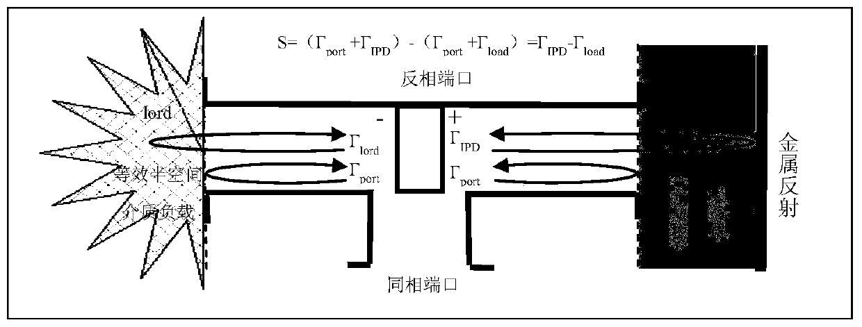
[0023] Step 1: Take the two symmetrical ports of the Magic Wave T as the reflection measurement ports, connect them to the radome under test and the equivalent half-space dielectric load respectively, and use the in-phase port and the anti-phase port of the Magic Wave T as the excitation signal input port and reflection Signal output detection port; such as figure 2 shown;

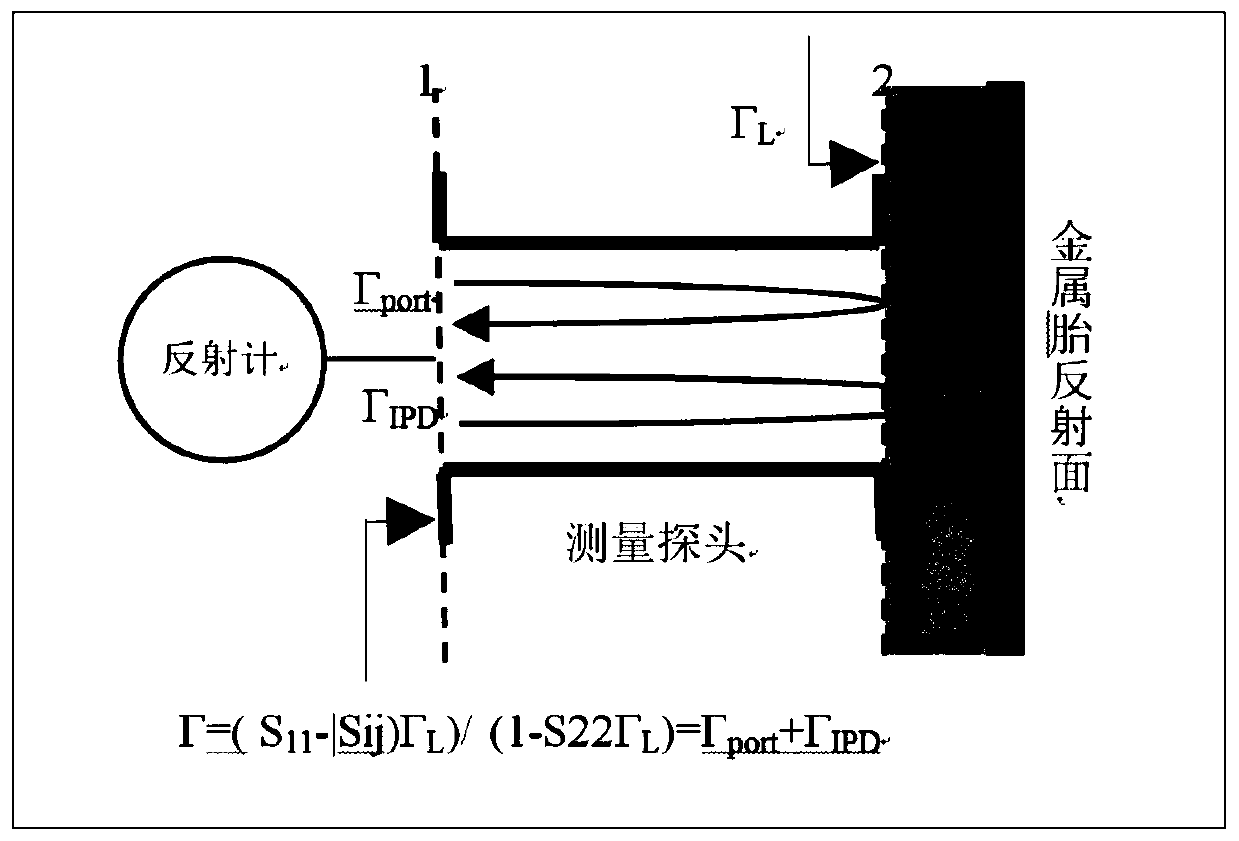
[0024] Step 2: Utilize the transmission characteristics of the waveguide magic T to isolate the signal pass-through from the input port to the output port, and symmetrically cancel the non-matching reflection component Γ port transmission to the output port;

[0025] Step 3: IPD reflection signal Γ of the radome under test IPD Equivalent IPD reflection ...


PUM


Abstract

The invention discloses a wide-working-frequency-band reflective electrical thickness test method, and belongs to the technical field of testing. Through the combination of equivalent half space medium load and waveguide magic T, automatic counteraction of mismatch reflection on the outer surface of a tested antenna housing is achieved; a reflected signal component containing IPD information is transmitted to an opposite-direction port and is naturally isolated from a same-direction port, and the reflection measurement is converted into transmission measurement, so that the measurement difficulty is reduced; an engineering application problem of a reflective electric thickness measurement method is solved, and good measurement linearity is provided.

Description

technical field [0001] The invention belongs to the technical field of testing, and in particular relates to a reflection-type electrical thickness testing method with a wide working frequency band. Background technique [0002] Electric thickness refers to the increase in wave number relative to the vacuum path of the same geometric size when the electromagnetic wave radiation passes through the non-vacuum medium space, which can be equivalent to the phase delay of the electromagnetic wave propagating in the medium relative to the vacuum increase, called insertion phase delay (IPD) . The IPD parameter is of great significance to the design of the radome and must be measured during the fabrication process. The traditional IPD test is to place the radome under test between the microwave transceiver antennas, and measure the transmission phase difference caused by different radome for comparative measurement, or compare it with the transmission phase without placing the radom...

Claims


Application Information

Patent Timeline
IPC IPC(8): G01B7/06G01R29/10
CPCG01B7/06G01R29/10
Inventor 郭利强吴强冷朋
Owner THE 41ST INST OF CHINA ELECTRONICS TECH GRP
Why Eureka
Try Eureka