Multi-user energy sharing method based on electricity-light-biogas multi-energy coupling system

A coupling system and multi-energy technology, which is applied in the field of multi-user energy sharing based on the electric-optical-marsh multi-energy coupling system, can solve the problems of energy waste and low utilization efficiency

Inactive Publication Date: 2019-11-08
HXXN ELECTRICITY
View PDF0 Cites 6 Cited by
  • Summary
  • Abstract
  • Description
  • Claims
  • Application Information

AI Technical Summary

Problems solved by technology

For this reason, the purpose of the present invention is to propose a multi-user energy sharing method based on the electric-optical-marsh multi-energy coupling system, to maximize the value of utilizing various energy sources, and to solve ener

Method used


Image

  • Multi-user energy sharing method based on electricity-light-biogas multi-energy coupling system
  • Multi-user energy sharing method based on electricity-light-biogas multi-energy coupling system
  • Multi-user energy sharing method based on electricity-light-biogas multi-energy coupling system

Examples


Embodiment 1

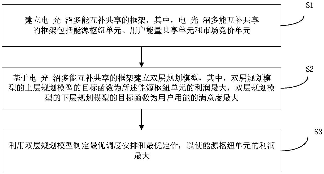
[0048] figure 1 It is a flow chart of the multi-user energy sharing method based on the electric-optical-marsh multi-energy coupling system according to the embodiment of the present invention. Such as figure 1 As shown, the method includes the following steps:

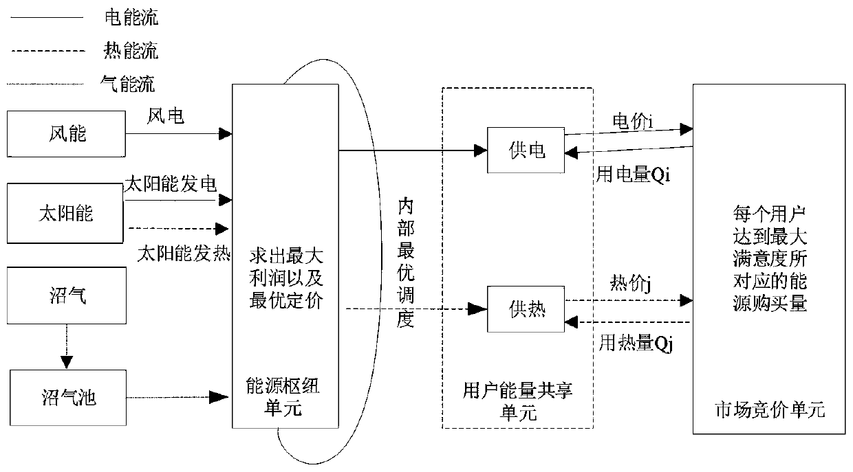
[0049] S1. Establish a framework for the complementary sharing of electricity-light-marsh multi-energy, where the framework for complementary sharing of electricity-light-marsh multi-energy includes an energy hub unit, a user energy sharing unit and a market bidding unit.

[0050] As an example, the electrical energy of the energy hub unit is provided by wind power, solar power and biogas through cogeneration units to power batteries, power boilers and participate in market bidding, and the thermal energy of the energy hub unit is generated by solar heating, electric boilers , Gas-fired boilers and biogas are provided by combined heat and power units to heat underground fermentation tanks and participate in market b...

Embodiment 2

[0098] Furthermore, the present invention also proposes a computer-readable storage medium.

[0099] In an embodiment of the present invention, a computer program is stored on a computer-readable storage medium, and when the computer program is executed by a processor, the above-mentioned multi-user energy sharing method based on the electric-optical-marsh multi-energy coupling system is realized.

[0100] In the computer-readable storage medium of the embodiment of the present invention, when the computer program corresponding to the above-mentioned multi-user energy sharing method based on the electro-optic-marsh multi-energy coupling system stored thereon is executed by the processor, by introducing the user side to participate in the energy The competition of transactions maximizes the value of various energy sources, solves the problems of wind energy, solar energy, biomass energy and other energy waste and low utilization efficiency, and also ensures that the energy hub u...


PUM


Abstract

The invention discloses a multi-user energy sharing method based on an electricity-light-biogas multi-energy coupling system, and the method comprises the following steps: building an electricity-light-biogas multi-energy complementary sharing framework which comprises an energy hub unit, a user energy sharing unit and a market bidding unit; establishing a double-layer planning model based on theelectricity-light-biogas multi-energy complementary sharing framework, the objective function of an upper-layer planning model of the double-layer planning model is the maximum profit of the energy hub unit, and the objective function of a lower-layer planning model of the double-layer planning model is the maximum satisfaction degree of user energy consumption; and formulating optimal schedulingarrangement and optimal pricing by utilizing the double-layer planning model so as to maximize the profit of the energy hub unit. The method solves the problems of waste and low utilization rate of wind energy, light energy, biomass energy and the like, ensures that the energy hub unit can obtain the maximum profit, and realizes win-win of users and the energy hub unit.

Description

technical field [0001] The invention relates to the technical field of energy management, in particular to a multi-user energy sharing method based on an electric-optical-marsh multi-energy coupling system. Background technique [0002] Although the multi-energy coupling hub in which biogas participates can alleviate the volatility and randomness brought about by wind and solar energy, and can reduce the cost of the system, there are still problems of low energy utilization, and phenomena such as abandoning wind and light occur from time to time, resulting in waste of energy. Contents of the invention [0003] The present invention aims to solve one of the technical problems in the related art at least to a certain extent. For this reason, the purpose of the present invention is to propose a multi-user energy sharing method based on the electric-optical-marsh multi-energy coupling system, to maximize the value of utilizing various energy sources, and to solve energy waste...

Claims


Application Information

Patent Timeline
IPC IPC(8): G06Q10/04G06Q10/06G06Q50/06G06F17/13
CPCG06F17/13G06Q10/04G06Q10/06315G06Q50/06Y02E40/70Y04S10/50
Inventor 周斌孟云帆李佳勇李文芳王怀智张宽
Owner HXXN ELECTRICITY
Why Eureka
Try Eureka