Aviation power supply signal multiplexing bus and transmission circuit thereof

A technology for power signal lines and power signals, applied in the field of avionics, can solve the problems of limiting the volume of sensors and controllers, large data of sensors and controllers, and the weight of the aircraft occupied by on-board cables, so as to reduce the number of physical connection cables. , reduce weight, reduce the effect of external interface

Inactive Publication Date: 2019-11-08
SHAANXI QIANSHAN AVIONICS
View PDF2 Cites 0 Cited by
  • Summary
  • Abstract
  • Description
  • Claims
  • Application Information

AI Technical Summary

Problems solved by technology

[0002] In airplanes and other aircraft, there are a large number of sensors and controllers. When the aircraft is designed as a whole, it is often necessary to provide power to such devices and additionally connect bus digital signals to realize the networking of sensors and controllers. and control, even if the device is small in size and power consumption, at least two types of buses are required for connection. Due to the huge data of the sensors and controllers on the aircraft, the cables on the aircraft occupy a large amount of weight of the aircraft.
[0003] At the same time, in order to be compatible with the transmission of power and signals, it is necessary to choose an aviation connector with a large number of pins, and then a relatively large aviation connector must be selected, thus limiting the size of sensors and controllers.

Method used


Image

  • Aviation power supply signal multiplexing bus and transmission circuit thereof
  • Aviation power supply signal multiplexing bus and transmission circuit thereof
  • Aviation power supply signal multiplexing bus and transmission circuit thereof

Examples


Embodiment Construction

[0024] The present invention is described in further detail below in conjunction with accompanying drawing:

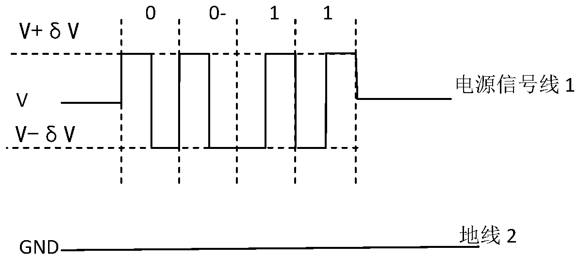
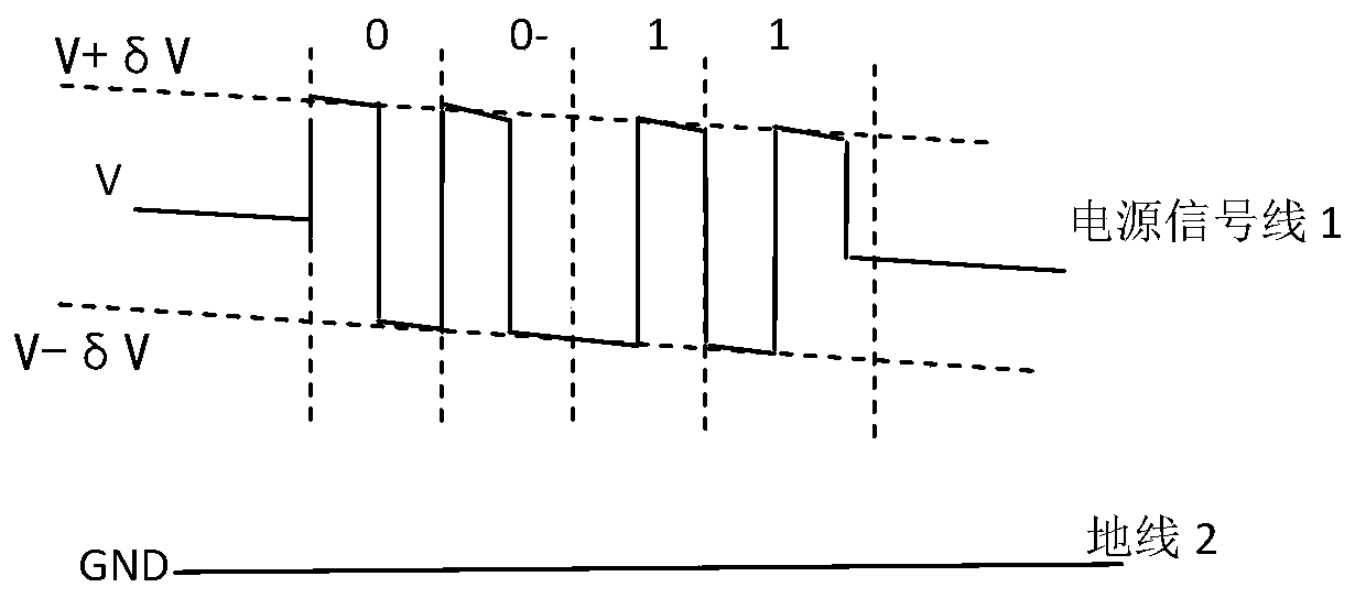
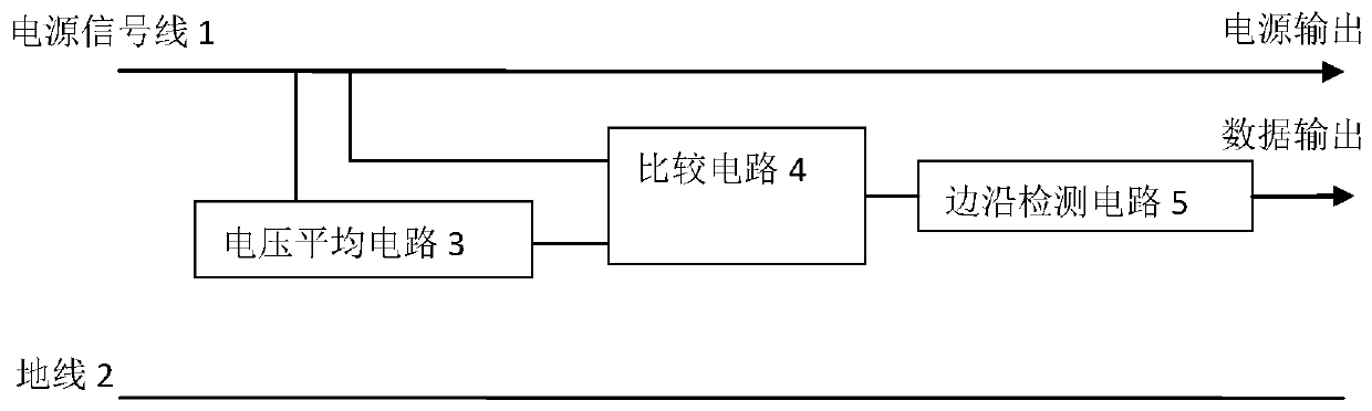
[0025] like Figure 1~2 As shown, an aviation power signal multiplexing bus of the present invention is composed of a power signal line 1 and a ground line 2. It is characterized in that the power signal line 1 is used to transmit DC power and digital signals, and the ground line 2 is used for current Return wire and signal reference. The voltage value on the power signal line 1 fluctuates δV up and down with the power supply voltage V to be transmitted as the reference level (δV>0). When the level jumps from V-δV to V+δV, it is recognized as 1, and jumps from V+δV When V-δV is recognized as 0, when the power supply V fluctuates, it will cause the voltage V on the power signal line 1 to follow the fluctuation, which does not affect the judgment of the logic value "1" and "0", and the continuous jump of "1" and "0" is realized For data transmission, the average voltag...


PUM


Abstract

The invention provides an aviation power supply signal multiplexing bus. The bus comprises a power supply signal line and a ground wire. The power supply signal line is used for transmitting a direct-current power supply and a digital signal. The ground wire is used for current loop and signal reference. The voltage value on the power supply signal line floats up and down for delta V by taking a power supply voltage V to be transmitted as a reference level. When the level jumps from V-delta V to V + delta V, the level is identified as 1. The level jumps from V + delta V to V-delta V. The levelis identified as 0. The data transmission is realized through continuous jumping of '1' and '0'. The energy transmission of a direct-current power supply is realized through transmission of power supply voltage V. According to the multiplex bus provided by the invention, the number of physical connection cables of sensors and controller equipment on an airplane at present can be reduced. The external interfaces of the sensors and the controller equipment can be remarkably reduced, so that the weight of the cables on the airplane is remarkably reduced.

Description

technical field [0001] The invention belongs to the technical field of avionics, and in particular relates to an avionics power supply signal multiplexing bus and an implementation method thereof. Background technique [0002] In airplanes and other aircraft, there are a large number of sensors and controllers. When the aircraft is designed as a whole, it is often necessary to provide power to such devices and additionally connect bus digital signals to realize the networking of sensors and controllers. And control, even if the size of the device and the power consumption is small, at least two types of buses are required for connection. Due to the huge data of the sensors and controllers on the aircraft, the cables on the aircraft occupy a large amount of weight of the aircraft. [0003] At the same time, in order to be compatible with the transmission of power and signals, it is necessary to choose an aviation connector with a large number of pins, and then a relatively la...

Claims


Application Information

Patent Timeline
Patent Type & Authority Applications(China)
IPC IPC(8): H04L12/40
CPCH04L12/40H04L2012/4028
Inventor 程金杨斌斌张柯季媛媛孙官中
Owner SHAANXI QIANSHAN AVIONICS
Why Eureka
Try Eureka