Rotating electric machine control device
A technology for rotating electrical machines and control devices, applied in motor control, control systems, vector control systems, etc., can solve problems such as increased calculation load, achieve the effect of suppressing the increase of calculation load and improving the accuracy of estimation
- Summary
- Abstract
- Description
- Claims
- Application Information
AI Technical Summary
Problems solved by technology
Method used
Image
Examples
Embodiment approach 1
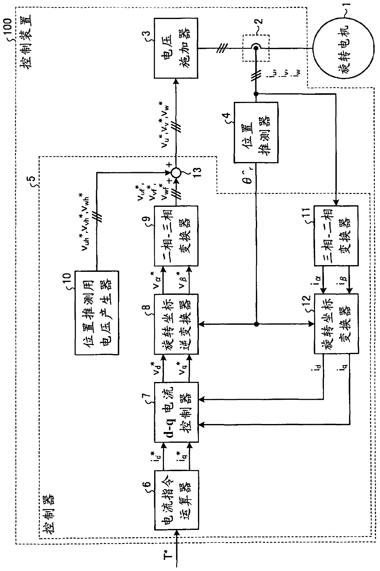
[0036] figure 1 It is a diagram showing the configuration of a control device for a rotating electrical machine according to Embodiment 1 of the present invention. Hereinafter, a "control device for a rotating electrical machine" may be simply referred to as a "control device". figure 1 The shown control device 100 includes: a voltage applicator 3, u * , v v * , v w * AC power is supplied; the current detector 2 detects the AC current supplied from the voltage applicator 3 to the rotating electrical machine 1, and outputs the detected AC current as the rotating electrical machine current i u i v i w ; The position estimator 4 uses the rotating motor current i detected by the current detector 2 u i v i w To calculate the estimated position θ^ r ; and the controller 5, so that the output torque of the rotating electrical machine 1 becomes the torque command value T * Calculate the rotating electrical machine voltage command v for driving the rotating electrical mach...
Embodiment approach 2
[0064] In Embodiment 1, the drive control of the rotating electrical machine 1 is performed on the rotation coordinates. Control on the rotating coordinates is widely used, and it is possible to drive and control the rotating electric machine 1 with high response. However, the control on the rotating coordinates requires transformation of the rotating coordinates and its control calculation. In Embodiment 2, a configuration example when the drive control of the rotating electric machine 1 is performed on the three-phase coordinates will be described.
[0065] Figure 6 It is a diagram showing the configuration of a control device for a rotating electrical machine according to Embodiment 2 of the present invention. The control device 100 of the first embodiment differs from the control device 100A of the second embodiment in that the controller 5A is used in the control device 100A instead of the controller 5 .
[0066] The controller 5A includes a position estimation voltage...
Embodiment approach 3
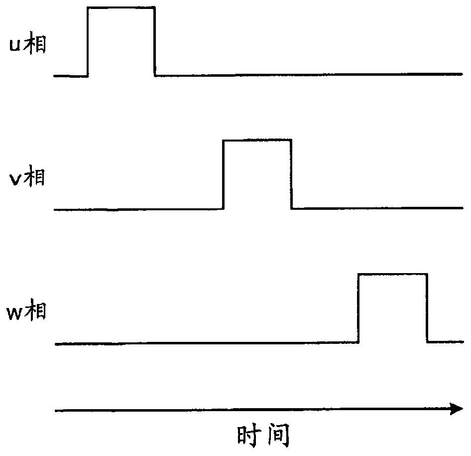
[0072] In Embodiments 1 and 2, the pulse-shaped position estimation voltage command v uh * , v vh * , v wh * . In Embodiment 3, a polyphase AC voltage is used as the position estimation voltage command v uh * , v vh * , v wh * .
[0073] Figure 7 It is a diagram showing the configuration of a control device for a rotating electrical machine according to Embodiment 3 of the present invention. The difference between control device 100 of Embodiment 1 and control device 100B of Embodiment 3 is that controller 5B is used instead of controller 5 and position estimator 4B is used instead of position estimator 4 in control device 100B.
[0074] The controller 5B has a current command calculator 6, a d-q current controller 7, a rotating coordinate inverse converter 8, a two-phase-three-phase converter 9, a position estimation voltage generator 10B, a three-phase-two-phase converter 11, a rotating A coordinate converter 12 and an adder 13 . In the controller 5B, the pos...
PUM
 Abstract
Description
Claims
Application Information
 - R&D
- Intellectual Property
- Life Sciences
- Materials
- Tech Scout
- Unparalleled Data Quality
- Higher Quality Content
- 60% Fewer Hallucinations
Browse by: Latest US Patents, China's latest patents, Technical Efficacy Thesaurus, Application Domain, Technology Topic, Popular Technical Reports.
© 2025 PatSnap. All rights reserved.Legal|Privacy policy|Modern Slavery Act Transparency Statement|Sitemap|About US| Contact US: help@patsnap.com


