Non-standard three-tool-bit shank structure for aluminum shell machine base machining

A technology of aluminum shell machine base and tool handle structure, which is applied to metal processing equipment, cutting tools for lathes, cutting blades, etc., can solve the problems of high production cost, many types and specifications of processing tools, and unfavorable production efficiency. The effect of long production cycle, improving processing efficiency and improving quality

Active Publication Date: 2019-11-12
无锡市亨达电机有限公司
View PDF12 Cites 0 Cited by
  • Summary
  • Abstract
  • Description
  • Claims
  • Application Information

AI Technical Summary

Problems solved by technology

[0003] For example, in the processing of the aluminum shell machine base in the prior art, the current common processing technology is: first process an end face, seam, and white section of one end, and then perform secondary clamping, and process the other end with the processed end face seam The end face, spigot, white section, and iron core file; each processing requires two knives to process, one knife to process the end face, and one knife to process the inner hole. It is impossible to achieve that one knife can process both the inner hole and the The seam can be processed, and multiple tool changes are required, which hinders the promotion of the one-knife hole process for the aluminum shell machine base, which is not conducive to the improvement of production efficiency, resulting in long production cycles of the aluminum shell machine base and labor intensity of operators in the prior art. Large size, high production cost, and many types and specifications of processing tools. There is a certain gap in the production of non-standard tools.

Method used


Image

  • Non-standard three-tool-bit shank structure for aluminum shell machine base machining
  • Non-standard three-tool-bit shank structure for aluminum shell machine base machining

Examples


Embodiment Construction

[0016] The present invention will be further described in detail below in conjunction with examples and specific implementations.

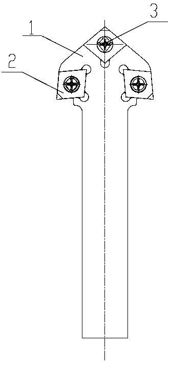
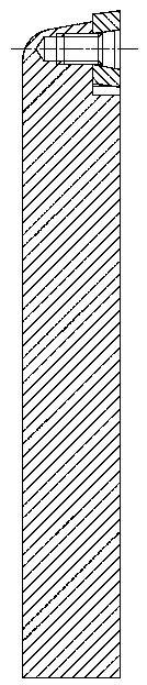
[0017] Such as figure 1 As shown, a non-standard three-bit tool holder structure for aluminum housing machine base processing. The structure includes a three-position tool holder 1 and an aluminum housing processing blade 2. Among them, the three-tool holder 1 has three head milling Blade mounting groove 11, the shape of the blade mounting groove 11 matches the shape of the corresponding aluminum shell processing blade 2. The aluminum shell processing blade 2 is connected and fixed with the three-position tool holder 1 through the blade mounting screw 3, and the mounting screw 2 is screwed in Mounting screw hole in the blade mounting groove 11.

[0018] The three-position tool holder 1 is made of T10A steel by quenching and tempering.

[0019] The blade 2 for processing the aluminum shell is a CCGT090404 PCD blade.

[0020] The blade mounting screw 3 is ...


PUM


Abstract

The invention discloses a non-standard three-tool-bit shank structure for aluminum shell machine base machining. The structure comprises a three-tool-station shank and aluminum shell machining tool blades, wherein three blade installing grooves are milled in the head part of the three-tool-station shank, the shape of the blade installing grooves is matched with the shape of the corresponding aluminum shell machining tool blades, the aluminum shell machining tool blades are fixedly connected with the three-tool-station shank through blade installing screws, and the installing screws are screwedinto installing screw holes in the blade installing grooves. The structure has the advantages that the operation is simple, the problem that the aluminum shell machine base requires tool replacementfor multiple times during machining in the prior art is solved, one shank is provided with the three blades, the machining efficiency of the aluminum shell machine base is improved, and the problems that the aluminum shell machine base is long in production period, high in operating labor intensity, high in production cost and large in machining tool model specification are solved. All machining surfaces of the machine base are machined through the promoted process of one-time clamping and one-tool machining, so that the repeated positioning errors are reduced, the concentricity of machining of the machine base is improved, and the machining quality of the machine base is improved.

Description

Technical field [0001] The invention relates to a non-standard three-head tool holder structure for machining an aluminum shell machine base. Background technique [0002] In the current tool industry, ordinary standard tools are the dominant tool, and special non-standard tools are rarely produced. Due to the production cycle and cost, many good processes cannot be implemented. It is impossible to process many parts with only one tool, and multiple tool changes and adjustments are required to complete the part processing. [0003] For example, in the processing of aluminum housings in the prior art, the current common processing technology is: first process an end face, stop, and white section at one end, and then perform secondary clamping, and position the other end with the processed end stop. The end face, the spigot, the white section, and the iron core gear; each processing requires two knives for processing, one for the end face, and the other for the inner hole. It is imp...

Claims


Application Information

Patent Timeline
Patent Type & Authority Applications(China)
IPC IPC(8): B23B27/00B23B27/16
CPCB23B27/00B23B27/1662B23B2205/10B23B2210/02
Inventor 洪泽伟
Owner 无锡市亨达电机有限公司
Why Eureka
Try Eureka