
Injection mold for machining plastic part with gate shearing structure

A technology of injection mold and shearing structure, which is applied in cleaning methods and utensils, cleaning methods using tools, chemical instruments and methods, etc., can solve problems such as low production efficiency, uneven cutting surface, and affecting the overall appearance of products, and achieve Avoid blocking, beautiful surface effect

Inactive Publication Date: 2019-11-12
张育闻
View PDF0 Cites 0 Cited by
  • Summary
  • Abstract
  • Description
  • Claims
  • Application Information

AI Technical Summary

Problems solved by technology

[0006] The purpose of the present invention is to provide a kind of injection mold for plastic part processing that is provided with nozzle shearing structure, to solve the injection mold on the market currently proposed by the above-mentioned background technology, in the process of using and producing plastic parts, after injection molding is completed, Since there will be a certain length gap between the sprue of the injection mold and the inner cavity of the mold, there will be a certain length of pouring burr on the injection molded product. When the product is taken out, it is often necessary to manually remove it. Unevenness affects the overall appearance of the product. When the cutting knife removes the pouring burrs on the injection molding product, it is easy to cause the burrs to adhere to the surface of the cutting knife. If manual cleaning is used, it is not only troublesome to clean, time-consuming and laborious, but also easy to operator hand injury problems

Method used


Image

  • Injection mold for machining plastic part with gate shearing structure
  • Injection mold for machining plastic part with gate shearing structure
  • Injection mold for machining plastic part with gate shearing structure

Examples


Embodiment Construction

[0030] Based on the embodiments of the present invention, all other embodiments obtained by persons of ordinary skill in the art without making creative efforts belong to the protection scope of the present invention.

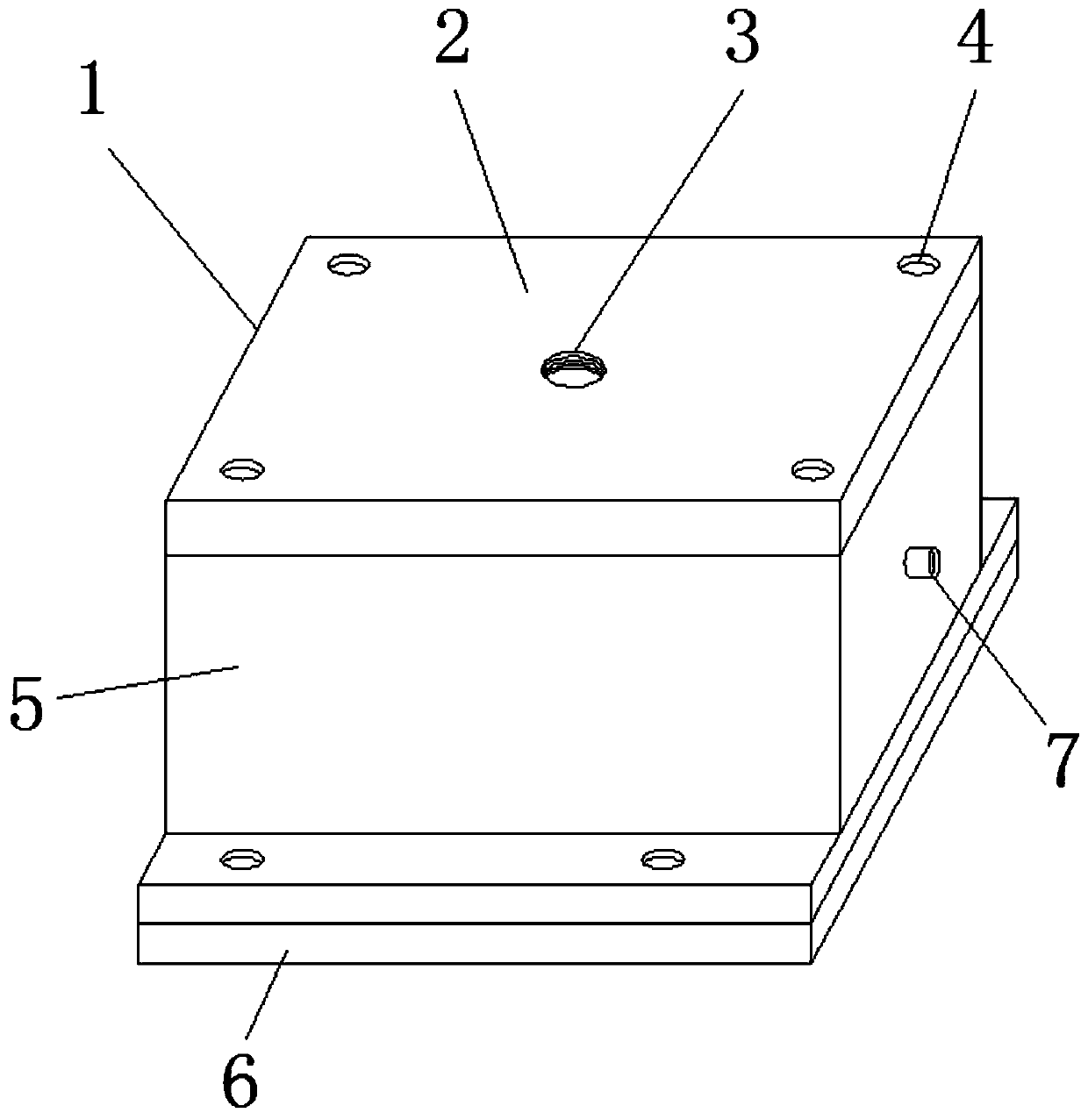
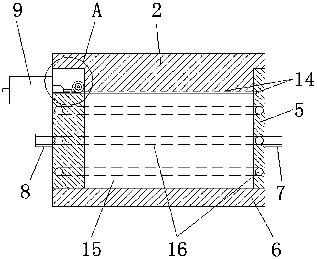
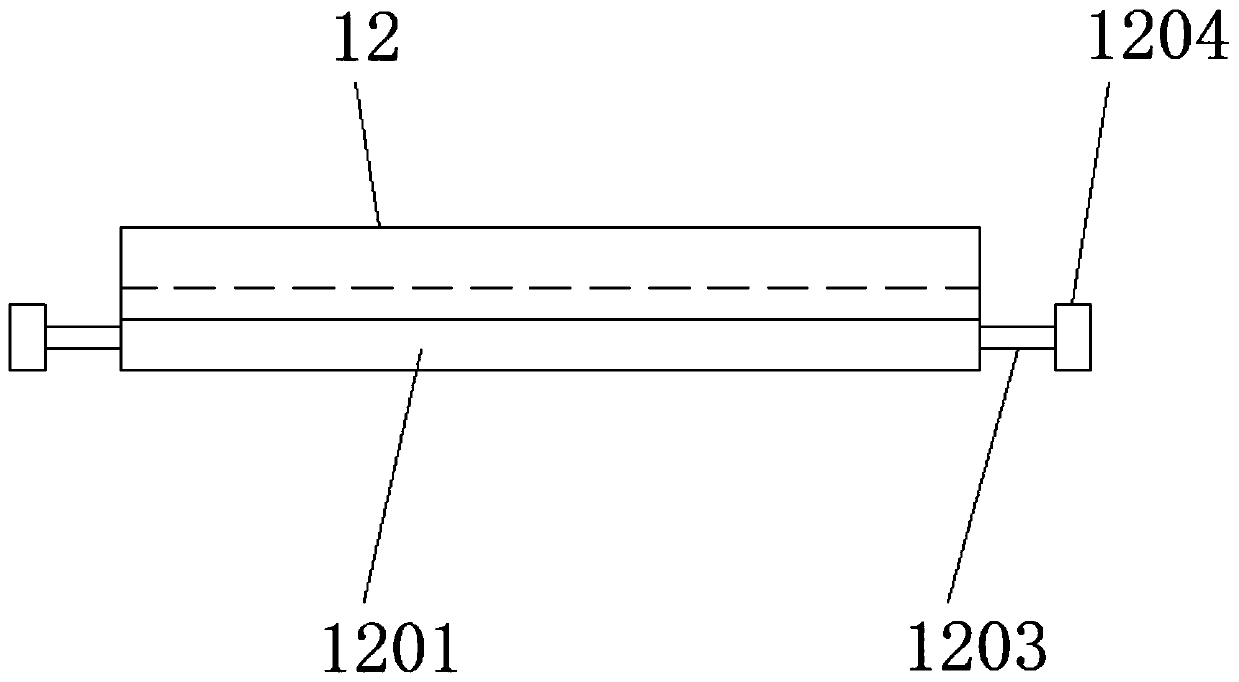
[0031] see Figure 1-11 , the present invention provides a technical solution: an injection mold for processing plastic parts provided with a nozzle shear structure, including an injection mold main body 1, a mold top plate 2, an injection port 3, fastening bolts 4, a mold middle shell 5, a mold Bottom plate 6, water inlet 7, water outlet pipe 8, telescopic cylinder 9, air pipe interface 10, telescopic frame 11, shear knife 12, knife edge 1201, fixed plate 1202, support rod 1203, roller 1204, cleaning roller 13, limit groove 14 , mold cavity 15, cooling pipe 16, sealing block 17, compression spring 18, hair brush 19, rotating shaft 20 and offset groove 21, a mold top plate 2 is arranged on the injection mold main body 1, and an injection molding port 3 is opene...


PUM


Abstract

The invention discloses an injection mold for machining a plastic part with a gate shearing structure. The injection mold comprises an injection mold main body, a mold top plate, an injection moldingport, a fastening bolt, a mold middle shell, a water inlet and a water outlet pipe. A mold top plate is arranged on the injection mold main body, wherein an injection molding opening is formed in themold top plate, and a sealing block is disposed at the bottom of the mold top plat; meanwhile, the mold top plate is connected with the mode middle shell through a fastening bolt; and the bottom end of the mold middle shell is connected with a mold bottom plate through a fastening bolt. A cleaning roller is arranged above a shearing knife, wherein a brush is arranged outside the cleaning roller, and the cleaning roller is connected with a rotating shaft. A mold cavity is formed in the middle of the mold middle shell, and a cooling pipe is embedded in the side wall of the mold middle shell. According to the injection mold for machining the plastic part with the gate shearing structure, smooth cutting of the injection-molded burrs can be realized, surface of an injection-molded product is attractive, and a cutting tool can be cleaned.

Description

technical field [0001] The invention relates to the technical field of injection molds, in particular to an injection mold for processing plastic parts provided with a nozzle shearing structure. Background technique [0002] Injection mold is a kind of accessory manufacturing device commonly used in industrial manufacturing. It can cool and shape the injection molding raw materials added to the inner cavity of the injection mold, and then manufacture accessories with corresponding structural shapes. Since the inner cavity of the injection mold can be processed according to needs The shape and size of the accessories are customized, and the manufacturing time is limited, and they can be recycled multiple times. Therefore, they are widely used in the manufacturing industry. [0003] However, the existing injection molds have the following problems in the process of using and producing plastic parts; [0004] 1. After the injection molding is completed, there will be a certain...

Claims


Application Information

Patent Timeline
Patent Type & Authority Applications(China)
IPC IPC(8): B29C45/38B29C45/17B08B1/02B08B1/04B08B1/20
CPCB29C45/38B29C45/1753B08B1/20B08B1/32B08B1/12
Inventor 张育闻
Owner 张育闻
Learn More