Magnetic fluid flywheel for spacecraft

A magnetic fluid and spacecraft technology, which is applied in space navigation equipment, space navigation vehicles, space vehicle guidance devices, etc., can solve undiscovered problems, achieve easy replacement, improve output torque and torque stability, and assemble high precision effect

Active Publication Date: 2019-11-12
BEIJING INST OF CONTROL ENG
View PDF6 Cites 6 Cited by
  • Summary
  • Abstract
  • Description
  • Claims
  • Application Information

AI Technical Summary

Problems solved by technology

However, the existing magnetic fluid technology is mostly applied to the gyroscope sensor for detecting angular motion. There is no application in the public information to control the motion of the magnetic fluid through active power supply to generate the angular momentum and output torque required by the star.

Method used


Image

  • Magnetic fluid flywheel for spacecraft
  • Magnetic fluid flywheel for spacecraft
  • Magnetic fluid flywheel for spacecraft

Examples


Embodiment 1

[0027] A magnetofluid flywheel for spacecraft includes a conductive fluid ring assembly, a magnetic steel assembly and two electrodes.

[0028] The conductive fluid ring assembly includes a lower sealing cover, a gland, a stem, a fluid shell, and a conductive fluid; the fluid shell is in sealing connection with the lower sealing cover and the gland at the same time, and the stem is simultaneously connected with the lower sealing cover and the gland Sealed connection; the lower sealing cover, the gland, the stem, and the fluid shell jointly form a conductive fluid cavity, and the conductive fluid is located in the conductive fluid cavity. Two electrodes are respectively connected with the stem and the fluid shell.

[0029] Both the lower sealing cover and the gland are made of non-conductive and non-magnetic non-metallic materials. Both the core column and the fluid shell are made of conductive and non-magnetic materials. Both the electrodes and the fluid housing are insulate...

Embodiment 2

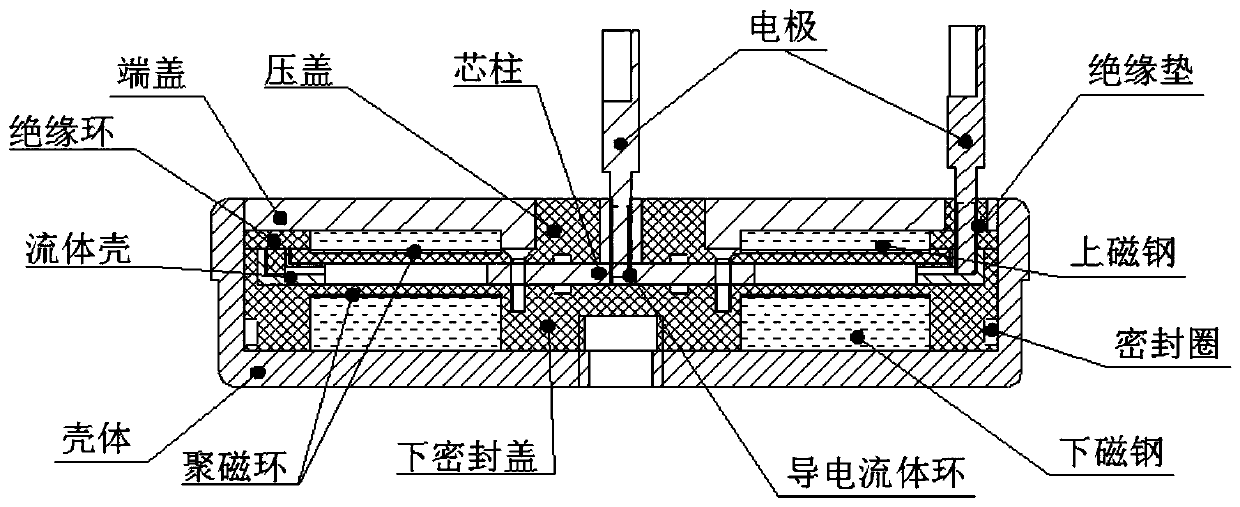
[0034] Such as figure 1 As shown, it is a cross-sectional view of a typical structure of a magnetic fluid flywheel in this embodiment, that is, the basic form of the present invention, including a conductive fluid ring assembly, a magnetic circuit assembly and electrodes.

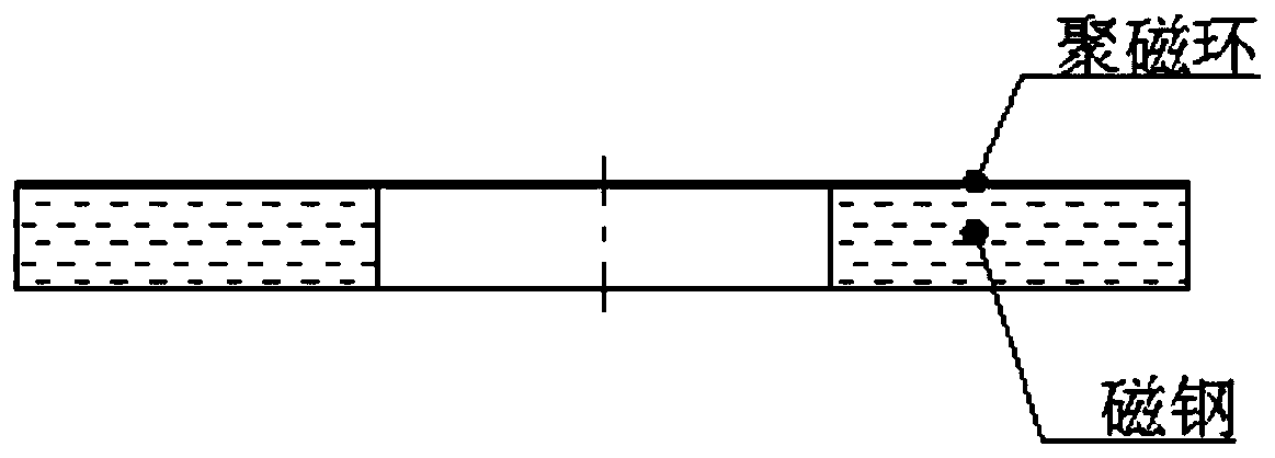
[0035] The rotation of the conductive fluid in the conductive fluid ring assembly can generate torque and angular momentum; the magnetic steel assembly is used to form the magnetic field used for the rotation of the conductive fluid; The inner and outer walls of the conductive fluid cavity form a potential difference, and the movement of charges causes the conductive fluid to rotate under force.

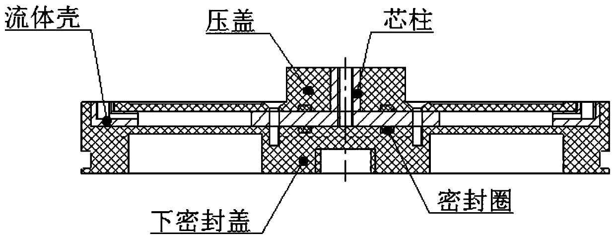
[0036] The conductive fluid ring assembly includes a lower sealing cover, a stem, a fluid shell, a gland, and a conductive fluid, such as figure 2 As shown, a conductive fluid cavity is formed between the lower sealing cover and the gland by the stem and the fluid shell, and the conductive fluid is sealed in the...


PUM


Abstract

The invention discloses a magnetic fluid flywheel for a spacecraft, which is capable of avoiding the problems of friction damping and abrasion of a conventional mechanical flywheel and prolonging theservice life and the overload resistance, and belongs to an attitude control system of the spacecraft. The magnetic fluid flywheel comprises a conductive fluid ring component, a magnetic steel component and electrodes. The magnetic fluid flywheel is simple in structure, high in assembly precision and convenient to replace. The magnetic steel component is used for providing a high-strength uniformvertical main magnetic field for a conductive fluid, a positive electrode and a negative electrode of the magnetic fluid flywheel are lead out by the two electrodes, the positive electrode and the negative electrode are electrified to enable the inner wall and the outer wall of a fluid ring to form a potential difference, the conductive fluid is stressed to rotate through the charge movement, andthe conductive fluid in the conductive fluid ring component can rotate to generate torque and angular momentum in order to realize the low-disturbance ultra-quiet index of the magnetic fluid flywheel.

Description

technical field [0001] The invention relates to a magnetofluid flywheel for spacecraft, which can be used as an attitude control actuator for a micro-nano satellite platform to provide torque and angular momentum required by a satellite attitude control system, and belongs to the spacecraft attitude control system. Background technique [0002] In recent years, in addition to the miniaturization and long life requirements of micro-nano satellite platforms, the requirements for pointing accuracy and attitude stability are also getting higher and higher. Existing conventional mechanical flywheel products have certain difficulties in improving the comprehensive performance of accuracy, volume and life, which has become a bottleneck for further improvement of the attitude control accuracy of the micro-nano satellite platform. Therefore, it is urgent to develop new micro-nano actuators to achieve ultra-quiet and low-disturbance functions. [0003] Compared with the mechanical fl...

Claims


Application Information

Patent Timeline
Patent Type & Authority Applications(China)
IPC IPC(8): B64G1/28
CPCB64G1/285
Inventor 杨磊张激扬杨屹周刚张强武登云张绍卫
Owner BEIJING INST OF CONTROL ENG
Why Eureka
Try Eureka