Food package vacuum sealing machine

A technology of vacuum sealing and food packaging, applied in packaging sealing/fastening, packaging, transportation packaging, etc., can solve the problems of high cost, increased factory floor space, large volume, etc., to increase applicability and airtightness , the effect of easy pulling out

Inactive Publication Date: 2019-11-12
何明
View PDF4 Cites 19 Cited by
  • Summary
  • Abstract
  • Description
  • Claims
  • Application Information

AI Technical Summary

Problems solved by technology

[0003] Most of the existing food packaging adopts the method of heat-sealing packaging, that is, placing the packaging bag vertically, adding food, and then heat-sealing the top of the packaging bag. At this time, the packaging bag contains food and air, and the air may contain a lot of bacteria and other microorganisms, so this packaging scheme is not conducive to the packaging and storage of food. Therefore, more and more manufacturers use the method of vacuumizing the packaging bag so that the food can be stored for a long time without adding preservative additives after packaging. , but the existing vacuum packaging and sealing equipment has a large volume. Each packaging bag that needs to be packaged needs to be placed in a sealed chamber for vacuum compression, and then sealed in the chamber and then transferred out of the chamber. The specific plan is as in the application number It is the "vacuum packaging machine" in the invention patent of 201410891253.5. This device has a large volume, and it needs more space to cooperate with the automatic feeding production line, which increases the floor space of the factory, and the manufacturing of the vacuum chamber of the device is complicated and the cost is high. , which is not conducive to start-up investment and use

Method used


Image

  • Food package vacuum sealing machine
  • Food package vacuum sealing machine
  • Food package vacuum sealing machine

Examples


Embodiment Construction

[0028] The following will clearly and completely describe the technical solutions in the embodiments of the present invention with reference to the accompanying drawings in the embodiments of the present invention. Obviously, the described embodiments are only some, not all, embodiments of the present invention.

[0029] In describing the present invention, it should be understood that the terms "upper", "lower", "front", "rear", "left", "right", "top", "bottom", "inner", " The orientation or positional relationship indicated by "outside", etc. is based on the orientation or positional relationship shown in the drawings, and is only for the convenience of describing the present invention and simplifying the description, rather than indicating or implying that the referred device or element must have a specific orientation, so as to Specific orientation configurations and operations, therefore, are not to be construed as limitations on the invention.

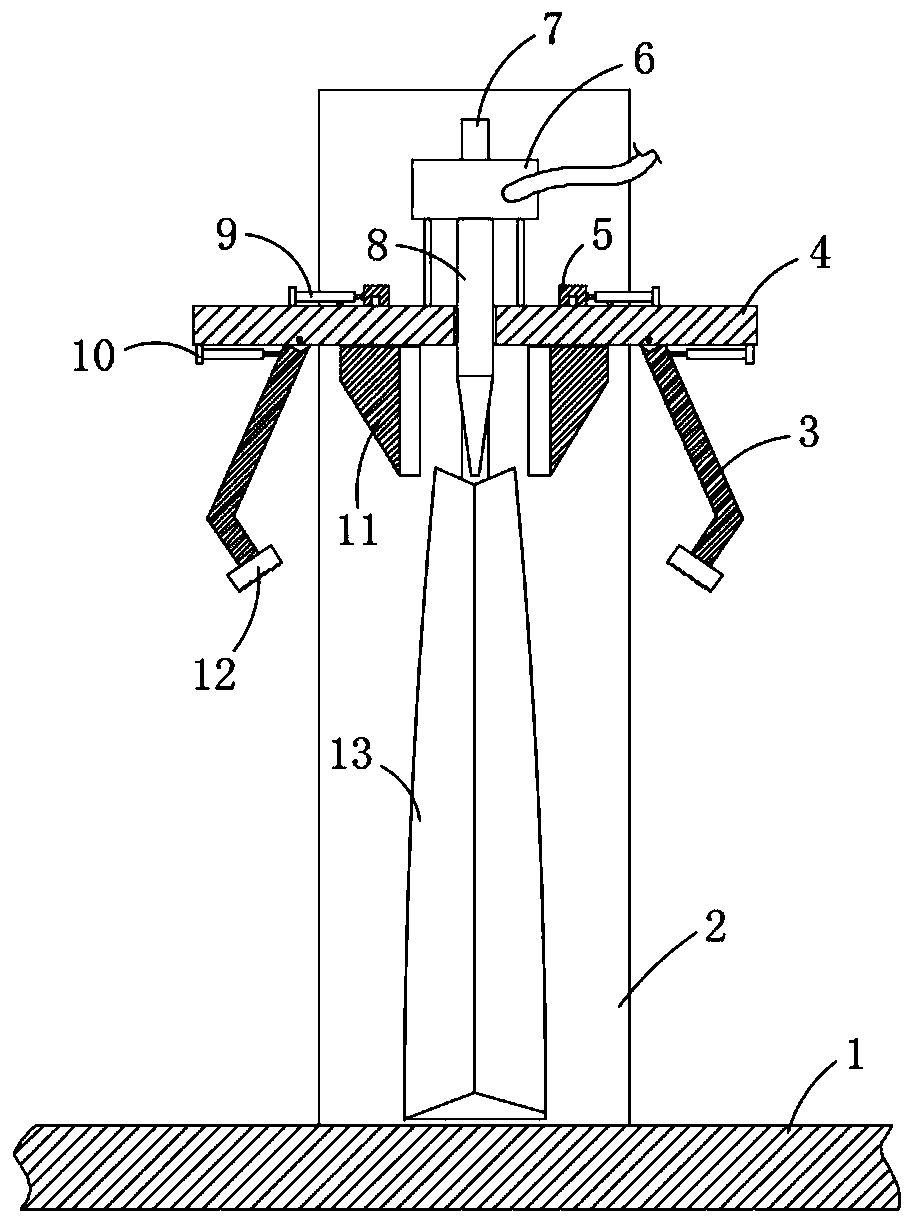
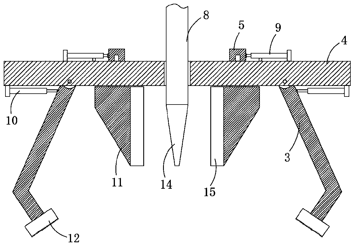
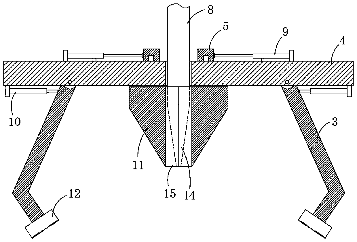
[0030] refer to Figure ...


PUM


Abstract

The invention discloses a food package vacuum sealing machine which comprises a worktable. A rail box is fixedly installed on the worktable. A rail groove is formed in the rail box. A sliding block isinstalled in the rail groove in a sliding manner, and multiple fixing rods are symmetrically fixedly installed at the lower end of the sliding block. A sealing plate is commonly fixedly installed atthe lower ends of the multiple fixing rods. The sealing plate is provided with a clamping sealing mechanism and a hot sealing mechanism. By means of the food package vacuum sealing machine, the sliding block is used for driving the clamping sealing mechanism and the hot sealing mechanism to move vertically, packaging bags with different height sizes can be subjected to vacuum sealing, an air guidepipe and the packaging bags can be sealed more tightly through the clamping sealing mechanism, vacuum pumping operation can be conducted conveniently, the hot sealing mechanism is used for driving aheating sealing bar to clamp the packaging bags for sealing through rotation of clamping plates, the speed is high, sealing is firm, the structures of the clamping sealing mechanism and the hot sealing mechanism are simple, the size is small, compared with a vacuum cavity, the occupied area is smaller, the cost is lower, and low-cost investment is facilitated.

Description

technical field [0001] The invention relates to the field of food production, in particular to a food packaging vacuum sealing machine. Background technique [0002] Food packaging is an integral part of food commodities and one of the main projects in the food industry process. It protects food and prevents biological, chemical, and physical external factors during the circulation of food from the factory to the hands of consumers. It can also have the function of maintaining the stable quality of the food itself. It is convenient for the consumption of food, and it first shows the appearance of the food and attracts consumption. It has value other than material costs. In the process of food packaging, the first thing to ensure It is safe and enables the packaged food to be stored for a longer period of time. [0003] Most of the existing food packaging adopts the method of heat-sealing packaging, that is, placing the packaging bag vertically, adding food, and then heat-se...

Claims


Application Information

Patent Timeline
Patent Type & Authority Applications(China)
IPC IPC(8): B65B31/06B65B51/10
CPCB65B31/06B65B51/10
Inventor 何明
Owner 何明
Why Eureka
Try Eureka