
Speed governor for emergency braking of traction elevator

A technology of emergency braking and speed limiter, which is used in elevators, transportation and packaging, and can solve problems such as complex overall structure.

Pending Publication Date: 2019-11-12
SHAANXI SIUSAI ELECTROMECHANICAL TECH CO LTD
View PDF1 Cites 2 Cited by
  • Summary
  • Abstract
  • Description
  • Claims
  • Application Information

AI Technical Summary

Problems solved by technology

[0005] The purpose of the present invention is to solve the problem that the existing elevator safety brake system needs to set the speed limiter and the brake device separately, so that the overall structure is complicated, and to provide a speed limiter for emergency braking of the traction elevator , it can not only sense the lifting speed of the car, but also realize two-way progressive braking for the car that deviates from the normal moving speed, so as to ensure the high safety of the car and help to simplify the structure of the braking system

Method used


Image

  • Speed governor for emergency braking of traction elevator
  • Speed governor for emergency braking of traction elevator
  • Speed governor for emergency braking of traction elevator

Examples


Embodiment 1

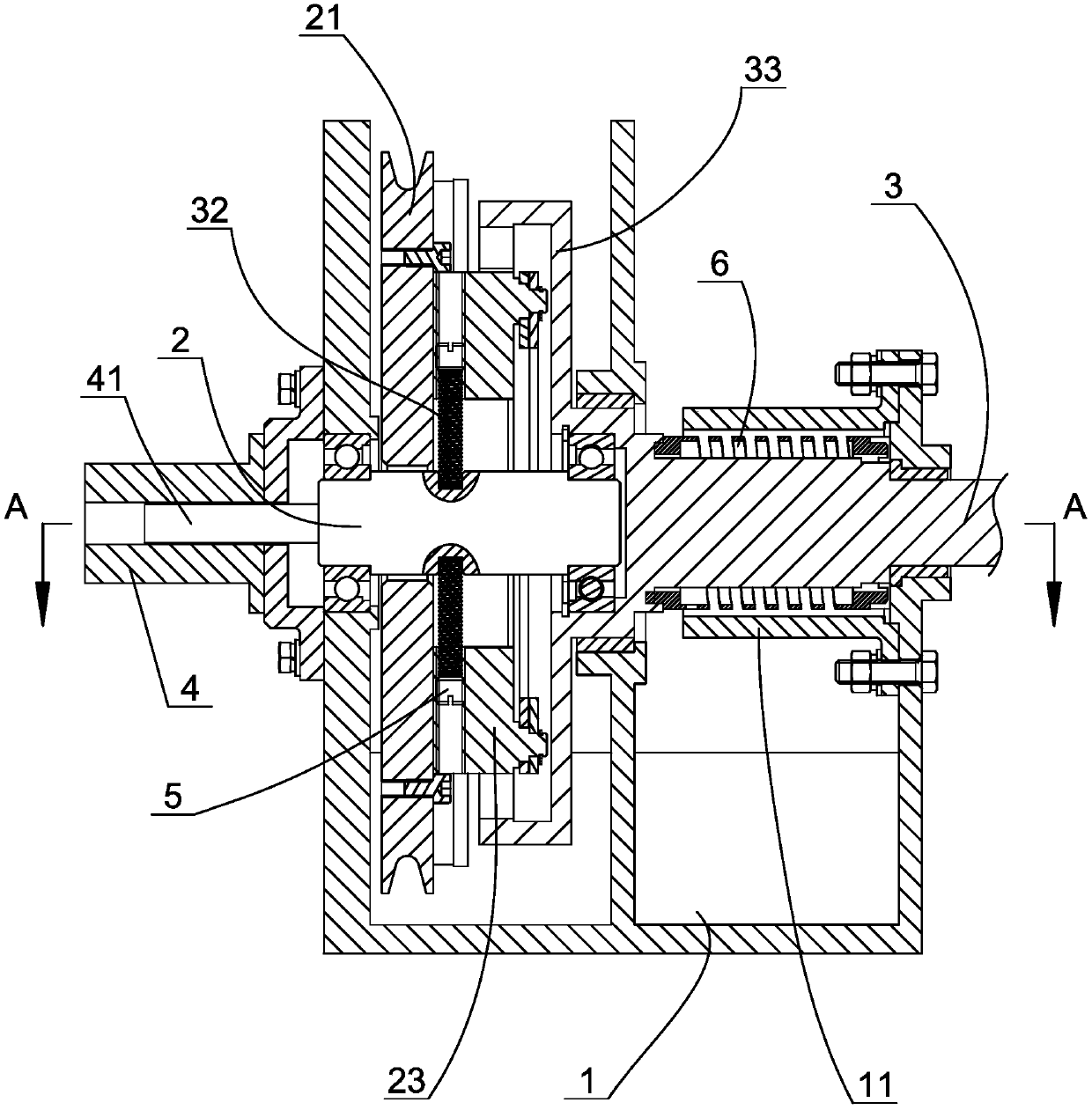
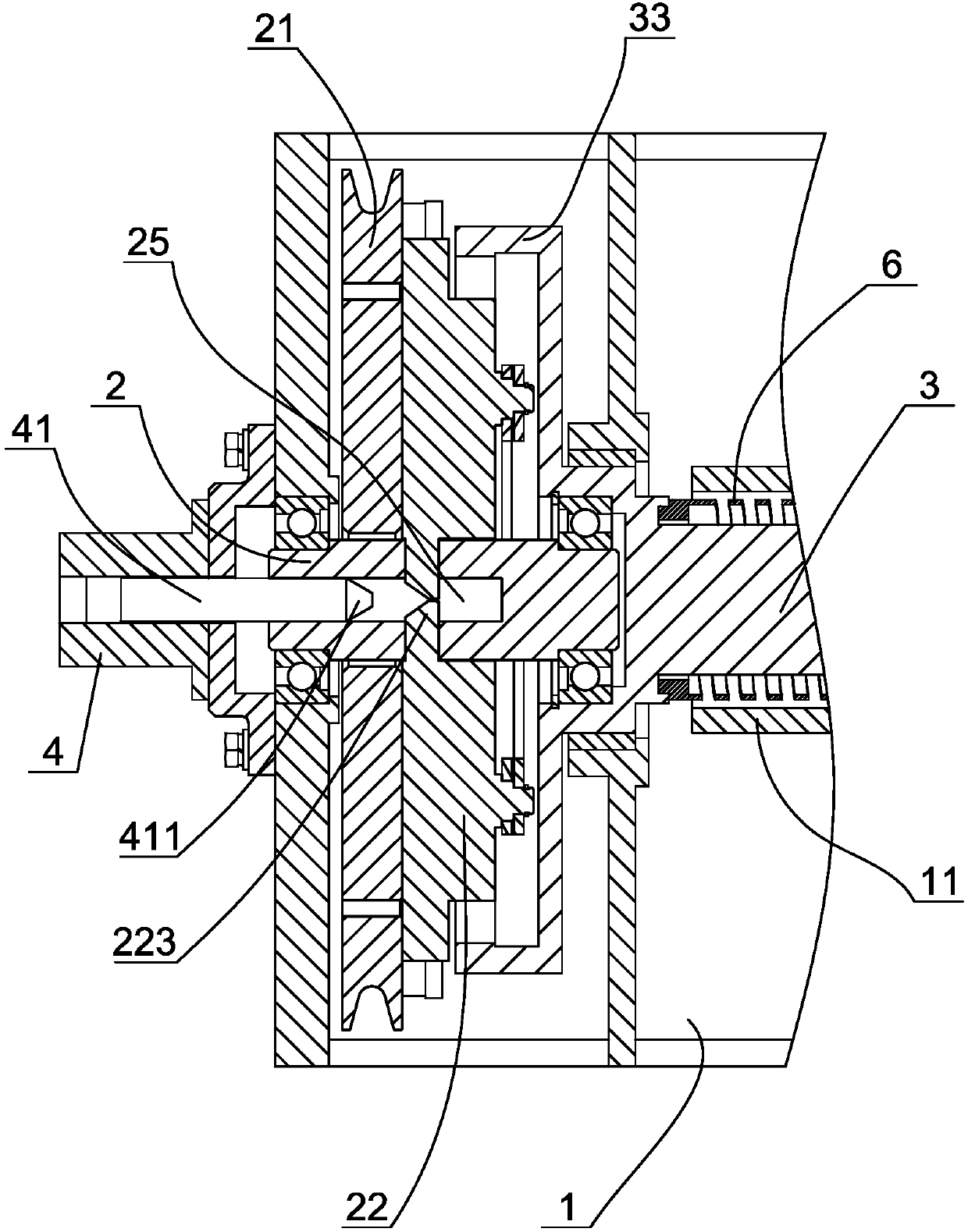
[0026] Embodiment 1: as figure 1 As shown, a speed governor for emergency braking of a traction elevator includes a frame 1, a driving shaft 2 arranged on the frame, a driven shaft 3 arranged coaxially with the driving shaft, and a pulley is keyed to the driving shaft 21. The steel wire rope for pulling the car is wound on the pulley. When the car lifts normally, the wire rope can drive the pulley to rotate, and then drive the drive shaft to rotate, and the rotation of the drive shaft has a linear relationship with the lift speed of the car.

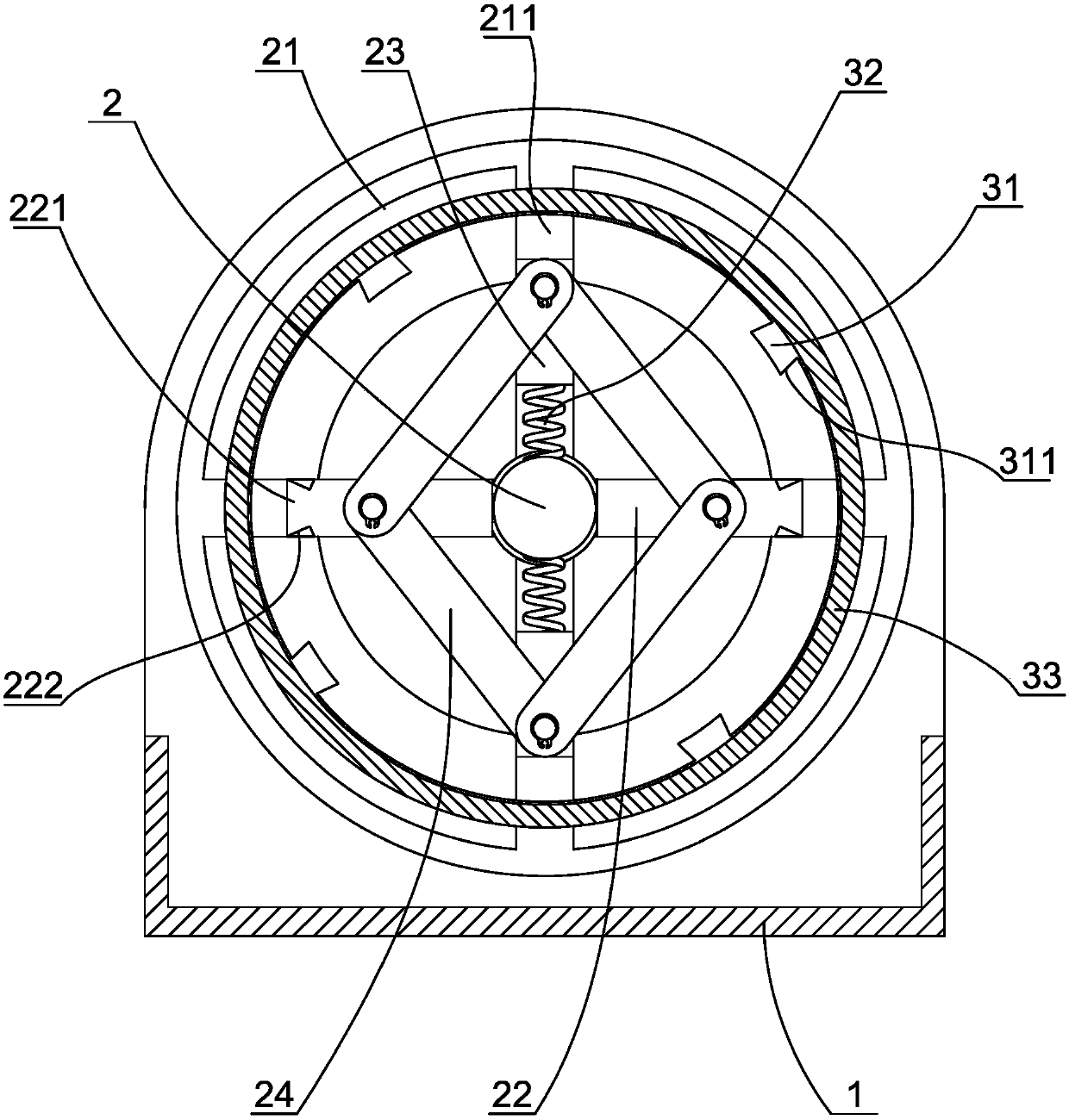
[0027] In addition, we can set a centrifugal clutch structure between the driven shaft and the driving shaft. When the speed of the driving shaft reaches or exceeds a rated value, the centrifugal clutch structure can make the driving shaft and the driven shaft rotate under the action of centrifugal force. The drive shaft can drive the driven shaft to rotate; when the speed of the drive shaft is lower than the rated value, the centrifuga...

Embodiment 2

[0035] Embodiment 2: In order to achieve a good buffering effect when the safety gear brakes, such as Figure 4 As shown, we can make the driven shaft and the overlapping sleeve form a rotational connection, and a limit sleeve 11 is fixedly connected on the frame, and the end of the driven shaft away from the driving shaft extends into the limit sleeve, and the driven shaft A gap is formed between the driven shaft and the limit sleeve, and a brake coil spring 8 is sleeved on the part where the driven shaft extends into the limit sleeve. One end of the brake coil spring is fixedly connected with the overlapping sleeve, and the other end of the brake coil spring is connected with the The driven shaft is fixedly connected, and the brake coil spring constitutes a damping spring, so that an elastic engagement can be formed between the driving shaft and the driven shaft. The rest of the structure is the same as that of Embodiment 1 and will not be described here.

[0036] When the ...


PUM


Abstract

The invention discloses a speed governor for emergency braking of a traction elevator. The speed governor comprises a driving shaft and a driven shaft, wherein the driving shaft is arranged on a machine frame and is associated with a steel wire rope, and the driven shaft is associated with a safety gear of a braking car; a centrifugal clutch structure is arranged between the driven shaft and the driving shaft; a limiting sleeve is arranged on the machine frame; a brake coil spring is arranged on the part, extending into the limiting sleeve, of the driven shaft in a sleeving manner; one end ofthe brake coil spring is connected to the machine frame; the other end of the brake coil spring is connected to the driven shaft; when the rotating speed of the driving shaft is greater than or equalto the rated rotating speed, the centrifugal clutch structure enables the driving shaft to be connected to the driven shaft; when the driven shaft rotates forward, the brake coil spring is gradually and tightly wound around the driven shaft until the driven shaft stops rotating; and when the driven shaft rotates reversely, the brake coil spring gradually releases and clings to the limiting sleeveuntil the driven shaft stops rotating. According to the speed governor, the lifting speed of the car can be sensed, and bidirectional progressive braking can be realized on the car deviating from thenormal moving speed.

Description

technical field [0001] The invention relates to the technical field of braking systems of traction elevators, in particular to a speed governor for emergency braking of traction elevators. Background technique [0002] In the traction elevator, the safety braking system is a mandatory safety device. The existing safety braking system includes a speed limiter for sensing the running speed of the car, and a The braking device for the elevator to realize mandatory braking. The speed governor usually includes a drive shaft on which a pulley is arranged, and the wire rope for pulling the car is wound on the pulley. When the car goes up and down, the wire rope drives the drive shaft to rotate through the pulley; when the car goes up and down at an overspeed, the speed limiter senses the speed of the drive shaft and acts, thereby driving the brake device to brake the car, thereby ensuring the safety of the elevator. Safety. It is stipulated in the national safety standard of the ...

Claims


Application Information

Patent Timeline
IPC IPC(8): B66B5/02B66B5/04B66B5/18
CPCB66B5/02B66B5/04B66B5/18
Inventor 陈庆邓健李军
Owner SHAANXI SIUSAI ELECTROMECHANICAL TECH CO LTD
Learn More