
Air duct structure and device equipped with air duct structure

A technology for air ducts and control devices, which is applied to pump devices, parts of pumping devices for elastic fluids, household appliances, etc., and can solve the problems that heating elements of cooling and heating tower fans cannot meet the air volume requirements at the same time, tower fans are dumped, etc. , to achieve the effect of low cost, small space occupation, and prevention of offset

Pending Publication Date: 2019-11-12
GREE ELECTRIC APPLIANCES INC
View PDF0 Cites 0 Cited by
  • Summary
  • Abstract
  • Description
  • Claims
  • Application Information

AI Technical Summary

Problems solved by technology

[0004] Therefore, the technical problem to be solved by the present invention is to overcome the defect that the heating element of the cooling and heating tower fan in the prior art cannot meet the air volume requirements and prevent the tower fan from toppling at the same time, so as to provide a device that can simultaneously meet the air volume requirements and prevent the tower fan from toppling. The device has a dumped air duct structure and a device with an air duct structure

Method used


Image

  • Air duct structure and device equipped with air duct structure
  • Air duct structure and device equipped with air duct structure
  • Air duct structure and device equipped with air duct structure

Examples


Embodiment Construction

[0038] The technical solutions of the present invention will be clearly and completely described below in conjunction with the accompanying drawings. Apparently, the described embodiments are some of the embodiments of the present invention, but not all of them. Based on the embodiments of the present invention, all other embodiments obtained by persons of ordinary skill in the art without making creative efforts belong to the protection scope of the present invention.

[0039] In addition, the technical features involved in the different embodiments of the present invention described below may be combined with each other as long as there is no conflict with each other.

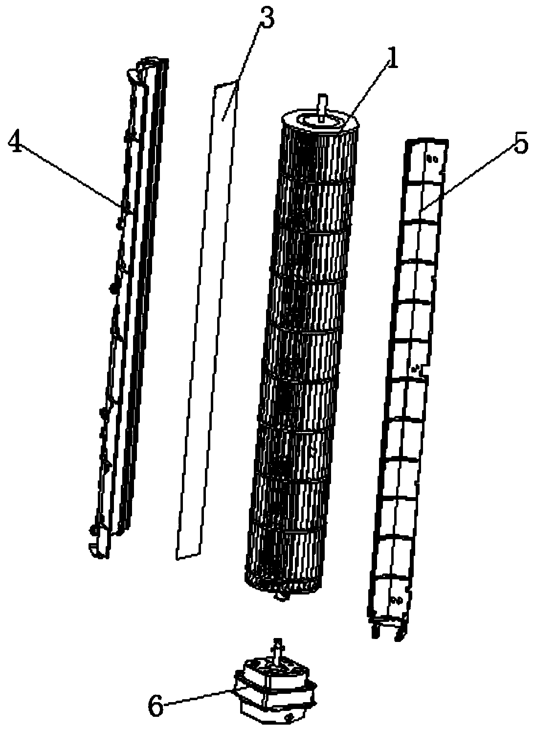
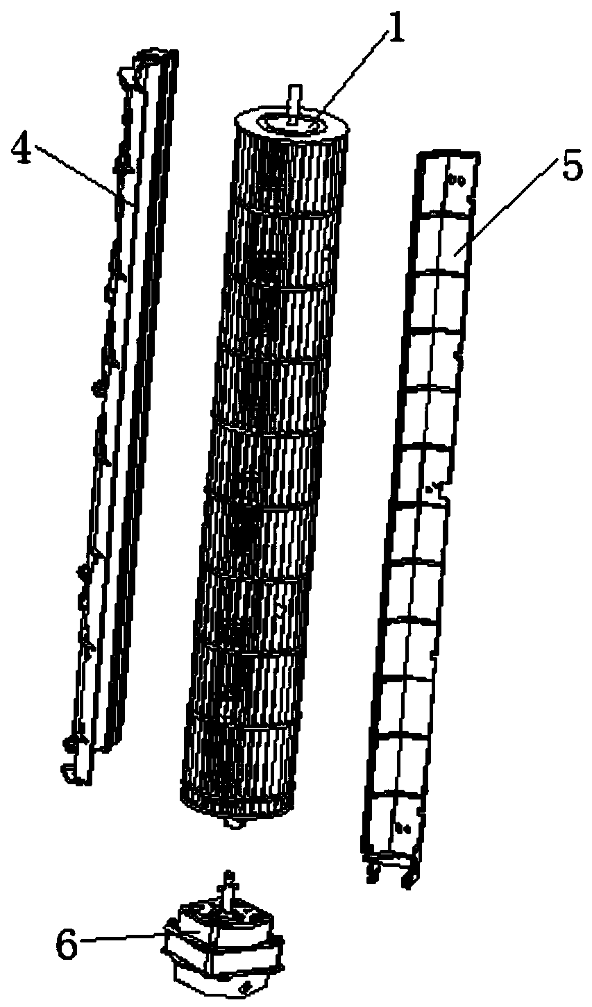
[0040] Such as Figure 1-Figure 4 As shown, this embodiment provides an air duct structure, including: a wind wheel 1, an air duct body 2, a heating structure and a control device.

[0041] The wind wheel 1; the air duct body 2 is arranged on the outside of the wind wheel 1 and forms an air duct with the win...


PUM


Abstract

The present invention relates to the technical field of household appliances, in particular to an air duct structure and a device equipped with the air duct structure. The air duct structure comprisesan air wheel, an air duct body, a heating structure and a control device, wherein the air duct body is arranged on the outer side of the air wheel; an air duct is formed between the air duct body andthe air wheel; the heating structure is suitable for heating air in the air duct; and the control device is electrically connected with the heating structure, and suitable for controlling the heatingstructure to start and stop when the air wheel rotates. The air duct structure provided by the invention has the beneficial effects that the air in the air duct is heated through the arrangement of the heating structure, so that the heating structure can be arranged on the air wheel or the air duct body, and the air can be heated by the heating structure when flowing through the air duct, ratherthan the fact that the heating structure is arranged at an air outlet or an air outlet of a housing; accordingly, the influence of the heating structure on the air volume can be prevented; and meanwhile, no moving mechanism is arranged, so that the heating structure can be prevented from moving, the deviation of the gravity center of the device can be prevented, and the device can be prevented from toppling.

Description

technical field [0001] The invention relates to the technical field of household appliances, in particular to an air duct structure and a device with the air duct structure. Background technique [0002] With the improvement of people's living standards and the higher and higher requirements for the living environment, the types of products used are increasing, and the requirements for the practicability of the products are getting higher and higher. The cooling and heating tower fan with this function came into being. [0003] Most of the cooling and heating tower fans in the prior art place the heating element directly in front of the grille of the air inlet or air outlet of the casing, and the heating element is fixed on the casing through the heating element bracket, so that in the cold wind mode, the existence of the heating element will Affects the air volume and air speed; in order to prevent the heating element from affecting the air output and air speed, a small nu...

Claims


Application Information

Patent Timeline
IPC IPC(8): F24F5/00F24F13/00F24F11/89F04D29/42F04D29/28F04D27/00F04D25/08
CPCF04D25/08F04D27/00F04D29/283F04D29/4233F24F5/0096F24F11/89F24F13/00F24F2221/18F24F2221/34
Inventor 刘哲徐余良丁睿陈志聪林达浩梁健华陈正超
Owner GREE ELECTRIC APPLIANCES INC
Learn More