
Heat dissipation device

A technology of heat dissipation device and heat dissipation parts, which is applied in the direction of modification through conduction heat transfer, cooling/ventilation/heating transformation, electrical components, etc., which can solve the problems of narrow internal space, unsuitable technical requirements, and unsuitable installation of fans, etc., to achieve The effect of good cooling effect

Pending Publication Date: 2019-11-12
ASIA VITAL COMPONENTS (CHINA) CO LTD
View PDF0 Cites 0 Cited by
  • Summary
  • Abstract
  • Description
  • Claims
  • Application Information

AI Technical Summary

Problems solved by technology

[0003] The current heat dissipation device is to install solid heat dissipation fins on the upper side of the temperature chamber, and to enlarge the heat dissipation area by means of the solid heat dissipation fins to increase the heat dissipation effect, or to further install a fan to generate a large air flow for heat dissipation. However, the current mobile devices, personal computers , servers, communication chassis, base stations, or other systems or devices have a narrow internal space that is not suitable for installing fans, and the solid cooling fins will be affected by the thermal conductivity of the material itself, which will affect the cooling effect. The heat dissipation device of the fin no longer meets the technical requirements of the future industry

Method used


Image

  • Heat dissipation device
  • Heat dissipation device
  • Heat dissipation device

Examples


Embodiment Construction

[0038] The above-mentioned objects and structural and functional characteristics of the present invention will be described based on the preferred embodiments of the accompanying drawings.

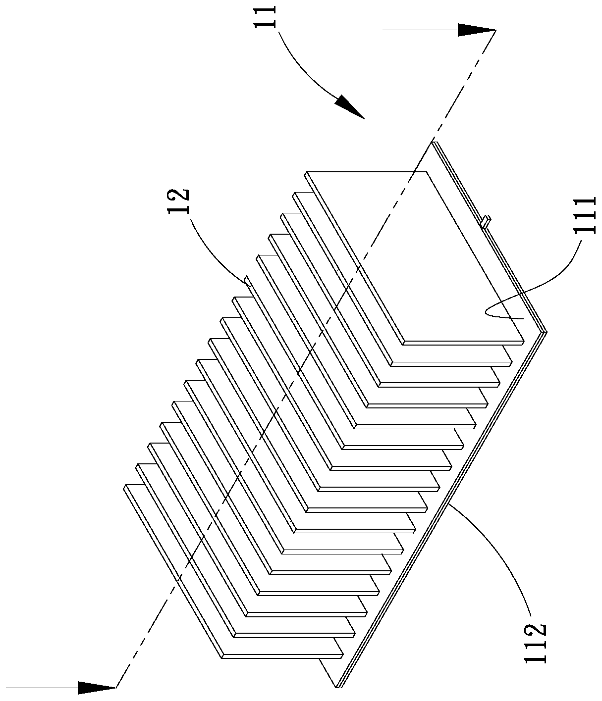
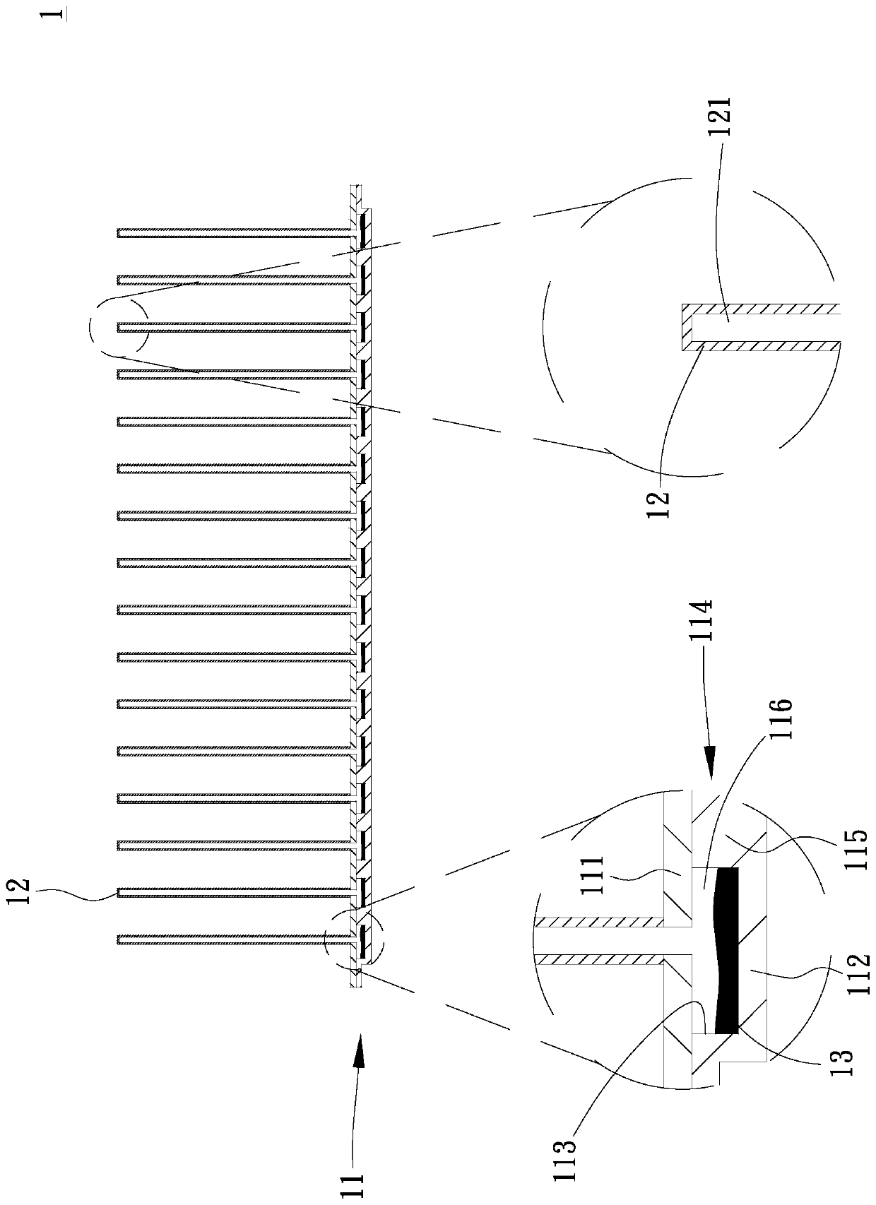
[0039] Please refer to figure 1 and figure 2 , Are the three-dimensional combined view and combined cross-sectional view of the first embodiment of the heat sink of the present invention. As shown in the figure, the heat sink 1 of the present invention is applied to a heat source that requires heat dissipation in an electronic device. The device 1 is contact-mounted on one or more heating elements (not shown) provided on a board (such as a circuit board or a motherboard) of the electronic device to dissipate the heating elements. The heating element is not limited to the above-mentioned central processing unit and display processing chip. In specific implementation, the heating element can be selected as a transistor or power element on a South Bridge or North Bridge chip or a circuit board o...


PUM


Abstract

The invention provides a heat dissipation device including a base having a first chamber, wherein the first chamber has a plurality of partitions separating the first chamber to form a plurality of compartments, the plurality of compartments are not connected to each other and are provided with first working fluids, the upper side of the base is provided with a plurality of two-phase flow heat dissipation fins, second chambers are respectively formed inside the plurality of two-phase flow heat dissipation fins, and the plurality of compartments and the plurality of second chambers are selectedto be in communication with each other or not connected to each other, thereby achieving a good heat dissipation effect.

Description

Technical field [0001] The invention relates to a heat dissipation device, in particular to a heat dissipation device which is provided with a heat dissipation chamber inside a heat dissipation fin and a base for the circulation of working fluid, so as to effectively achieve a good heat dissipation effect. Background technique [0002] Current mobile equipment, personal computers, servers, communication cases, base stations, or other systems or devices, with the advancement of science and technology, their computing functions and efficiency are gradually becoming stronger, and their internal heating elements (such as but not limited to chips and various power components) ) High heat is generated during operation, so the heat of the heating element must be dissipated first. In order to prevent the heating element from overheating and causing the heating element to fail, a heat sink is usually installed on the heating element to increase the service life of the heating element. [00...

Claims


Application Information

Patent Timeline
Patent Type & Authority Applications(China)
IPC IPC(8): H05K7/20
CPCH05K7/20336H05K7/2039
Inventor 刘汉敏张健吕星星
Owner ASIA VITAL COMPONENTS (CHINA) CO LTD
Learn More