Wastewater introducing structure of sewage treatment system

A sewage treatment system and wastewater technology, applied in water/sewage treatment, water/sludge/sewage treatment, filtration treatment, etc., can solve the problems of solid waste backlog, pipeline blockage, soil damage, etc. Easy to install effect

Active Publication Date: 2019-11-15
彭素荣
View PDF10 Cites 1 Cited by
  • Summary
  • Abstract
  • Description
  • Claims
  • Application Information

AI Technical Summary

Problems solved by technology

[0002] Nowadays, with the rapid development of industry and cities, a large amount of sewage is produced. These sewage are by-products of rapid development. Sewage pollutes water sources and also damages soil. Centralized treatment of sewage has become the theme of current environmental protection. , the existing sewage treatment system needs to clean up the solid waste in it before treating the sewage. If the solid waste is not treated, it will cause the blockage of the pipeline during subsequent treatment, and the existing solid waste separation mostly uses screens Intercept and remove solid waste, this method is likely to cause solid waste to accumulate at the screen and block the sewage inlet pipe
[0003] Notification number CN203634904U discloses a spiral trough that can quickly remove sewage solid waste, including a filter trough outer barrel, a filter trough inner barrel installed in the filter trough outer barrel, and a spiral blade placed in the filter trough inner barrel , a sealing cover, and a reducer and a motor placed at one end of the outer barrel of the filter tank. One end of the outer barrel of the filter tank is open and a sewage outlet is provided at the bottom. The solid waste discharge port extending from the opening end of the outer bucket of the filter tank, a number of filter holes arranged on the outer periphery of the inner bucket of the filter tank, and the sewage inlet located on the top of the inner bucket of the filter tank, the outer bucket of the filter tank The solid waste discharge port is trumpet-shaped and tilts outward. The device needs to open the sealing cover to clean up the solid waste inside. When the waste accumulated in the pipeline reaches a certain amount and is not cleaned up in time, it will easily cause the overall blockage of the pipeline.
[0004] The notification number CN207856469U discloses an anti-clogging sewage treatment device, which includes a base. The left and right sides of the base are symmetrically provided with rollers to facilitate the handling of the device. A mounting plate is provided above the base, and both sides of the lower end of the mounting plate pass through the supporting columns It is connected and fixed with the base. A crushing box is provided in the middle of the upper end of the installation plate, and a feeding hopper is provided at the feeding port in the middle of the upper end of the crushing box. The support column is connected by rotation, and the crushed solid waste fragments of the treatment device are easy to accumulate on the filter screen, causing the entire device to be blocked

Method used


Image

  • Wastewater introducing structure of sewage treatment system
  • Wastewater introducing structure of sewage treatment system
  • Wastewater introducing structure of sewage treatment system

Examples


Embodiment 1

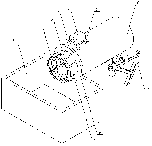
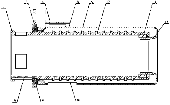
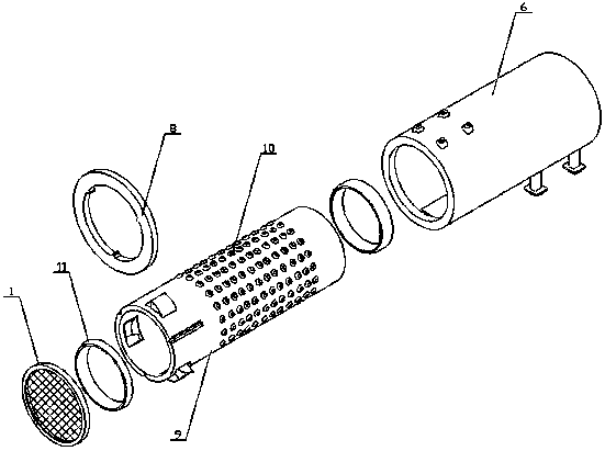
[0029] A waste water introduction structure of a sewage treatment system in the present invention is realized in the following way: a waste water introduction structure of a sewage treatment system in the present invention consists of a baffle (1), a guide shell (2), a drive gear (3), a motor (4), and a fixed Seat (5), shell pipe (6), support frame (7), driven gear (8), inner spiral pipe (9), solid waste bin (10), support bearing (11), drainage groove (12), It is composed of torsion spring (13), sewage inlet pipe (14), auxiliary flow plate (15), groove (16) and water hole (17). The top of the solid waste bin (10) is an open structure, and the outer shell One end of the pipe (6) is placed on the solid waste bin (10), and the support frame (7) is placed at the bottom of the other end of the shell pipe (6). The support frame (7) is composed of upper and lower parts, and the two parts are connected to each other Hinged, the other end of the shell tube (6) is reversely bent into th...

Embodiment 2

[0033] The difference between this embodiment and Embodiment 1 is: the guide shell (2) is a fan-shaped structure, and the guide shell (2) is provided with a garbage discharge port (18) facing the solid waste bin (10); , the garbage outlet (18) of the fan-shaped guide shell (2) is larger, which is convenient for garbage discharge, and the garbage outlet (18) faces the solid garbage bin (10), so that the garbage can be discharged directly along the garbage outlet under the action of centrifugal force In the solid waste bin (10), avoid discharge from other directions and fly away;

[0034] The present invention also relates to a self-adaptive adjustment method of the garbage conveying speed of the inner spiral pipe (9), which is characterized in that it comprises the following steps:

[0035] A. The flowmeter reads the sewage flow information in the sewage pipe;

[0036] B. The signal converter converts the data detected by the flowmeter and sends it to the data processor that h...


PUM


Abstract

The invention discloses a wastewater introducing structure of a sewage treatment system. According to the introducing structure, waste in sewage is separated by cooperation of an inner rotary pipe andan outer shell pipe, the waste is pushed to a shield cover through flow assisting pieces, and then the waste is discharged to a solid waste box through a guide shell for storage. The structure is characterized in that the top of the solid waste box has an open structure, one end of the outer shell pipe is placed on the solid waste box, a supporting frame is placed at the bottom of the other end of the outer shell pipe, the supporting frame is composed of an upper part and a lower part, and the two parts are hinged; and the other end of the outer shell pipe is bent reversely towards the interior of the outer shell pipe to form a sewage inlet pipe, one end of the inner rotary pipe is placed in the outer shell pipe and is connected with the sewage inlet pipe through a supporting bearing, theother end of the inner rotary pipe passes out from one end of the outer shell pipe, and the supporting bearing is arranged between the inner rotary pipe and the other end of the outer shell pipe, andthe shield cover is placed on the other end of the inner rotary pipe and is located above an opening of the solid waste box.

Description

technical field [0001] The invention relates to a waste water introduction structure of a sewage treatment system, which relates to a structure for guiding the sewage into the treatment system when the sewage enters the sewage treatment system, and belongs to the field of sewage treatment. In particular, it relates to an introduction structure that isolates garbage in sewage through the cooperation of the inner spiral tube and the outer tube, and pushes the garbage to the baffle through the auxiliary flow sheet, and then discharges the garbage into the solid garbage bin through the guide shell for storage. Background technique [0002] Nowadays, with the rapid development of industry and cities, a large amount of sewage is produced. These sewage are by-products of rapid development. Sewage pollutes water sources and also damages soil. Centralized treatment of sewage has become the theme of current environmental protection. , the existing sewage treatment system needs to clea...

Claims


Application Information

Patent Timeline
Patent Type & Authority Applications(China)
IPC IPC(8): B01D33/067B01D33/11B01D33/74B01D33/76C02F1/00
CPCB01D33/067B01D33/11B01D33/74B01D33/76C02F1/001
Inventor 彭素荣
Owner 彭素荣
Why Eureka
Try Eureka