Heavy road lifting method based on multi-stage composite telescopic hydraulic cylinder

A technology of telescopic hydraulic cylinder and two-stage cylinder, which is applied in the direction of lifting device, fluid pressure actuating device, etc., can solve the problems of affecting the lifting work efficiency, slow extension speed, vibration and impact, etc. The impact frequency of level change and the effect of increasing the expansion and contraction speed

Active Publication Date: 2019-11-15
BEIJING INST OF SPECIALIZED MACHINERY
View PDF5 Cites 0 Cited by
  • Summary
  • Abstract
  • Description
  • Claims
  • Application Information

AI Technical Summary

Problems solved by technology

At present, large-scale heavy-duty lifting equipment mostly adopts traditional plunger or piston-type multi-stage hydraulic cylinders. The plungers or pistons at each level need to be extended step by step, and the extension speed is relatively slow.
In addition, the plungers or piston rods at all levels need to be changed. When changing the level, the effective working area of ​​the hydraulic cylinder changes sharply, resulting in a sudden change in the system pressure and cylinder movement speed, which in turn causes collisions and vibration shocks, which not only affects the reliability of mechanical equipment, but also Affect lifting work efficiency
In response to the needs of hydraulic elevators and high-altitude operating vehicles, synchronous telescopic multi-stage hydraulic cylinders have appeared in recent years. Although this type of hydraulic cylinder has the advantages of fast movement speed and no impact of changing stages, under heavy loads, the hydraulic cylinder The pressure in the cavity is relatively high, and the external dimensions of the cylinder are relatively large, so it is not suitable for heavy-duty lifting occasions where the installation space is limited

Method used


Image

  • Heavy road lifting method based on multi-stage composite telescopic hydraulic cylinder
  • Heavy road lifting method based on multi-stage composite telescopic hydraulic cylinder
  • Heavy road lifting method based on multi-stage composite telescopic hydraulic cylinder

Examples


Embodiment Construction

[0028] In order to make the purpose, content, and advantages of the present invention clearer, the specific implementation manners of the present invention will be further described in detail below in conjunction with the accompanying drawings and embodiments.

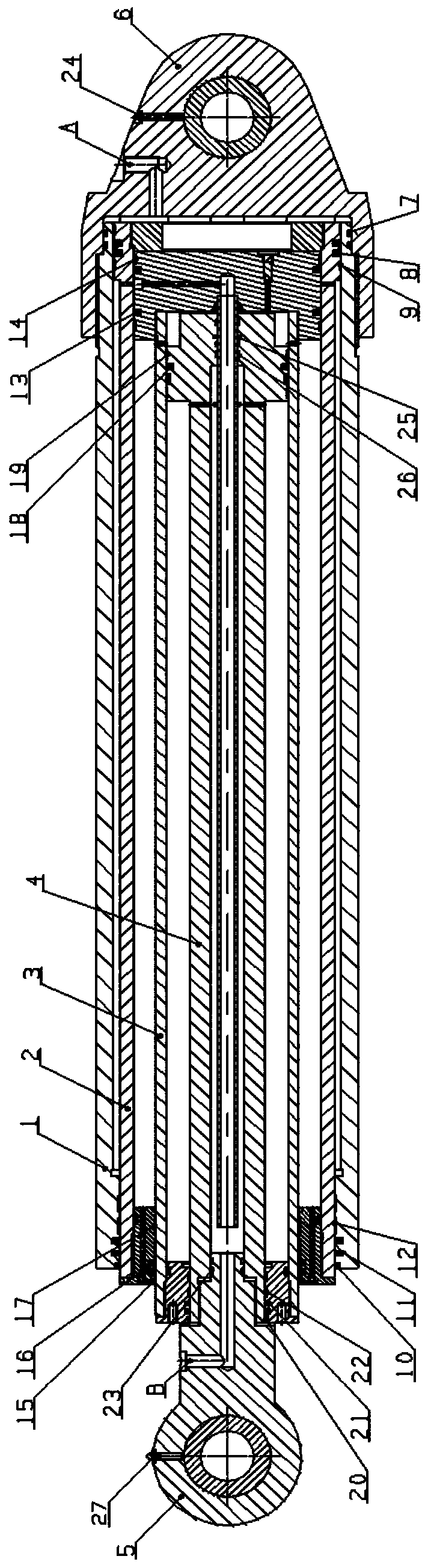
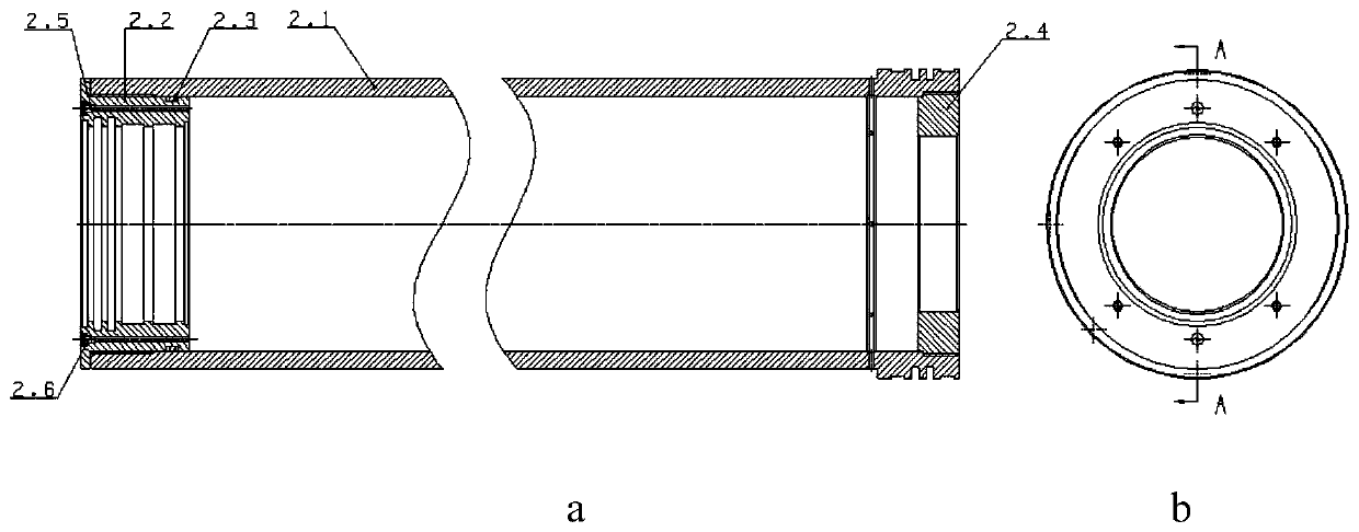
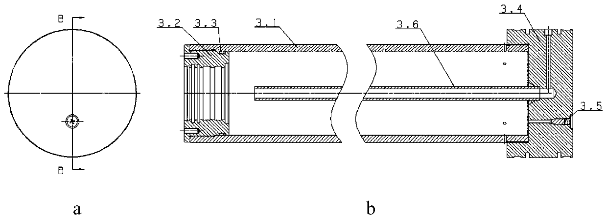
[0029] The present invention provides a heavy-duty lifting method based on a multi-stage composite telescopic hydraulic cylinder, which is realized based on a multi-stage composite telescopic hydraulic cylinder, such as figure 1As shown, the multi-stage composite telescopic hydraulic cylinder is designed to include cylinder barrel 1, first-stage cylinder 2, second-stage cylinder 3, third-stage cylinder 4, cylinder head 5, cylinder bottom 6 and O-rings of different specifications, lattice Lay ring, guide ring, dust ring and oil cup, of which:

[0030] The cylinder 1, the first-stage cylinder 2, the second-stage cylinder 3 and the third-stage cylinder 4 are sequentially nested from the outside to the inside. The cylinder...


PUM


Abstract

The invention relates to a heavy road lifting method based on a multi-stage composite telescopic hydraulic cylinder, and relates to the technical field of fluid transmission. Through matched design between multiple stages of cylinders, the telescopic speed of the heavy load multi-stage hydraulic cylinder can be obviously increased, the stage replacement impact frequency can be reduced, and the problems that machining and manufacturing of an existing composite telescopic hydraulic cylinder are difficult and assembling and advance oil filling cannot be achieved are solved. Synchronous errors generated in reciprocating motion of the hydraulic cylinder can be eliminated.

Description

technical field [0001] The invention relates to the technical field of fluid transmission, in particular to a heavy-duty lifting method based on a multi-stage composite telescopic hydraulic cylinder. Background technique [0002] The hydraulic cylinder is an important reciprocating motion actuator in the hydraulic system. Compared with single-stage hydraulic cylinders, multi-stage telescopic hydraulic cylinders have the advantages of shorter initial installation distance and longer stroke, and are widely used in large heavy-duty lifting equipment such as dump trucks and cranes. At present, large-scale heavy-duty lifting equipment mostly adopts traditional plunger or piston-type multi-stage hydraulic cylinders. The plungers or pistons at each level need to be extended step by step, and the extension speed is relatively slow. In addition, the plungers or piston rods at all levels need to be changed. When changing the level, the effective working area of ​​the hydraulic cylind...

Claims


Application Information

Patent Timeline
Patent Type & Authority Applications(China)
IPC IPC(8): B66F3/25B66F3/43F15B15/16F15B15/20
CPCB66F3/25B66F3/43F15B15/1404F15B15/1428F15B15/1461F15B15/165
Inventor 张振华王飞李春萍陈亮杨凯强曹秀荣
Owner BEIJING INST OF SPECIALIZED MACHINERY
Why Eureka
Try Eureka