A large battery installation

A battery installation device and large-scale technology, applied in the direction of lifting device, lifting frame, etc., can solve the problems of large battery volume and difficult screwing into the wall, etc., and achieve the effect of easy installation

Active Publication Date: 2020-11-17
张棉棉
View PDF5 Cites 0 Cited by
  • Summary
  • Abstract
  • Description
  • Claims
  • Application Information

AI Technical Summary

Problems solved by technology

[0003] Some batteries used in industry are large in size, and they need to be installed on a high wall and fixed with screws, but when installing this kind of battery, if people use all their strength to lift the battery , it is not easy to screw the screws on the battery into the wall

Method used


Image

  • A large battery installation
  • A large battery installation
  • A large battery installation

Examples


specific Embodiment approach 1

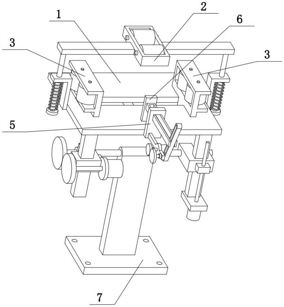
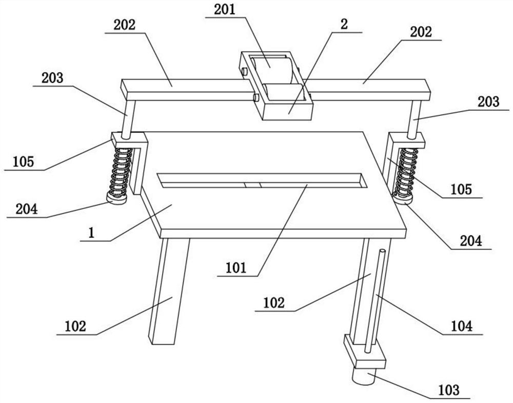
[0034] Combine below Figure 1-9 Describe this embodiment, the present invention relates to a mounting device, more specifically a large battery mounting device, including a flat plate 1, a horizontal slide hole 101, a clip seat 3, a side slot 301, a side wheel 302, and a stop pin 303 , convex plate 304, sliding seat 5, push plate 6 and push rod 601, the present invention can lift the battery with larger volume on the high place, is convenient to screw the screw on the battery into the wall, and is convenient for the installation of larger battery .

[0035] The flat plate 1 is provided with a horizontal sliding hole 101, the middle part of the front end of the flat plate 1 is fixedly connected with a sliding seat 5, the sliding seat 5 is slidably connected with a push rod 601, and the rear end of the push rod 601 is fixedly connected with a push plate 6, and the clamp seat 3. There are two on the left and right. The middle parts of the lower ends of the two clamping seats 3 ...

specific Embodiment approach 2

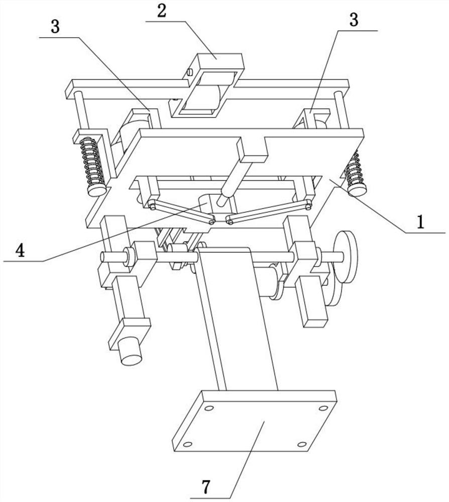
[0037] Combine below Figure 1-9To illustrate this embodiment, the large-scale battery installation device also includes a convex seat 106, an electric telescopic rod 107, a middle block 4 and an equal-length rod 401. The side is fixedly connected with an electric telescopic rod 107, and the left and right ends of the middle block 4 are all hingedly connected with an equal-length rod 401, and the other ends of the two equal-length rods 401 are respectively hingedly connected to the bottom of two convex plates 304, and the electric telescopic rod 107 The front end is fixedly connected on the middle block 4. When the electric telescopic rod 107 is stretched or shortened, it can drive the middle block 4 to slide forward or backward, and when the middle block 4 slides forward or backward, the two equal-length rods 401 can respectively drive the two convex plates 304 to approach each other or away, and then drive the two clamping seats 3 to approach or move away from each other, a...

specific Embodiment approach 3

[0039] Combine below Figure 1-9 To illustrate this embodiment, the large-scale battery installation device also includes a front extension rod 501, a motor II502, a gear I503, a short cylinder 602, a short cylinder chute 603, a chute rod 604, a short shaft 605, and a gear II606. The front side is fixedly connected with the front extension rod 501, the front extension rod 501 is fixedly connected with the motor II502, the output shaft of the motor II502 is fixedly connected with the gear I503, the chute rod 604 is provided with a short cylindrical chute 603, and the chute rod 604 The lower end of the shaft 605 is fixedly connected with a short shaft 605, the short shaft 605 is rotatably connected to the front end of the front extension rod 501, the left end of the short shaft 605 is fixedly connected with a gear II606, the gear II606 is meshed with the gear I503 for transmission, and the front end of the push rod 601 is fixedly connected with a short shaft. The cylinder 602 an...


PUM


Abstract

The invention relates to a mounting device, in particular to a large-scale battery mounting device. The device comprises a flat plate, a transverse sliding hole, clamping seats, side grooves, side rotating wheels, stop pins, convex plates, a sliding seat, a push plate and a push rod. According to the large-scale battery mounting device, a battery of larger size can be lifted at a high position, sothat a screw on the battery can be conveniently screwed into the wall, thus facilitating mounting of the battery of larger size. The flat plate is provided with the transverse sliding hole; the middle portion of the front end of the flat plate is fixedly connected with the sliding seat, wherein the sliding seat is slidably connected with the push rod, the rear end of the push rod is fixedly connected with the push plate; the two clamping seats are arranged on the left and right, wherein the middle portions of the lower ends of the two clamping seats are connected with the convex plates, and the two convex plates are slidably connected to the left and right ends of the transverse sliding hole; the lower ends of the two convex plates are fixedly connected with the stop pins, wherein the twostop pins are fit with the lower side of the flat plate; and the side grooves are formed in the two clamping seat, wherein the two side grooves are rotatably connected with a plurality of side rotating wheels, and axes of the plurality of side rotating wheels are in the vertical direction.

Description

technical field [0001] The invention relates to a mounting device, in particular to a large battery mounting device. Background technique [0002] A battery refers to a cup, tank or other container or part of a composite container that contains an electrolyte solution and a metal electrode to generate an electric current, and is a device that converts chemical energy into electrical energy. It has positive pole and negative pole. As technology advances, batteries generally refer to small devices that can generate electricity. Such as solar cells. The performance parameters of the battery mainly include electromotive force, capacity, specific energy and resistance. Using the battery as the energy source can obtain stable voltage, stable current, stable power supply for a long time, and a current that is little affected by the outside world, and the battery structure is simple, easy to carry, easy to charge and discharge, and is not affected by the external climate and temp...

Claims


Application Information

Patent Timeline
Patent Type & Authority Patents(China)
IPC IPC(8): B66F7/06B66F7/28
CPCB66F7/0641B66F7/28
Inventor 张棉棉
Owner 张棉棉
Why Eureka
Try Eureka