
Bearing platform construction process method within prefabricated vertical column range

A construction technology and column technology, which is applied to bridge parts, erection/assembly of bridges, bridges, etc., can solve problems such as increasing construction costs, unfavorable stress conditions of foundation piles, and complicated construction processes, and achieve the effect of ensuring integrity

Active Publication Date: 2019-11-15
BEIJING MUNICIPAL CONSTR +1
View PDF5 Cites 4 Cited by
  • Summary
  • Abstract
  • Description
  • Claims
  • Application Information

AI Technical Summary

Problems solved by technology

Caps are divided into high pile caps and low pile caps: low pile caps are generally buried or partially buried in the soil, high pile caps are generally exposed to the ground or water surface; high pile caps have a free length, There is no supporting body around it to jointly bear the horizontal external force, and the stress situation of the foundation pile is extremely unfavorable. The internal force and displacement of the pile body are larger than that of the low pile cap under the same horizontal external force, and its stability is worse than that of the low pile cap. When the cap is buried deep, necessary protective measures should be taken for adjacent buildings and municipal facilities, and the position of the column is not easy to determine, the construction process is more complicated, and the construction cost is greatly increased

Method used


Image

  • Bearing platform construction process method within prefabricated vertical column range
  • Bearing platform construction process method within prefabricated vertical column range
  • Bearing platform construction process method within prefabricated vertical column range

Examples


Embodiment Construction

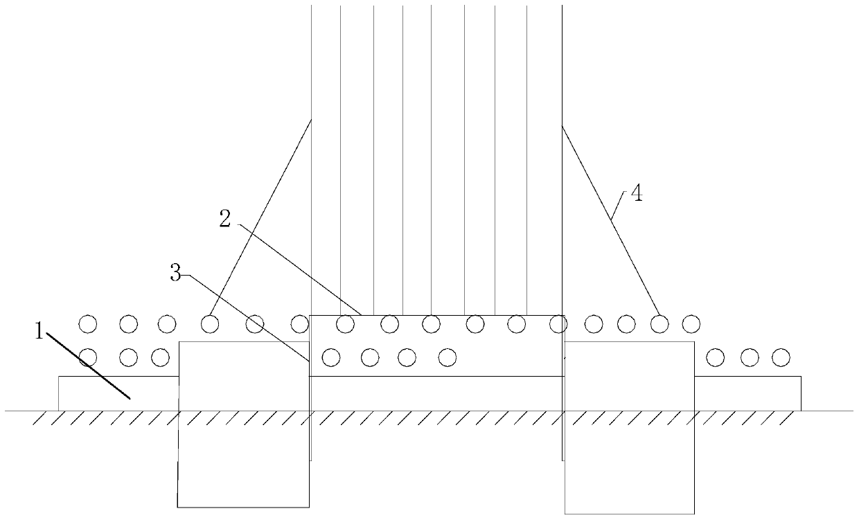
[0032] The technical solution of the present invention will be further described in detail below in conjunction with the accompanying drawings, but the protection scope of the present invention is not limited to the following description.

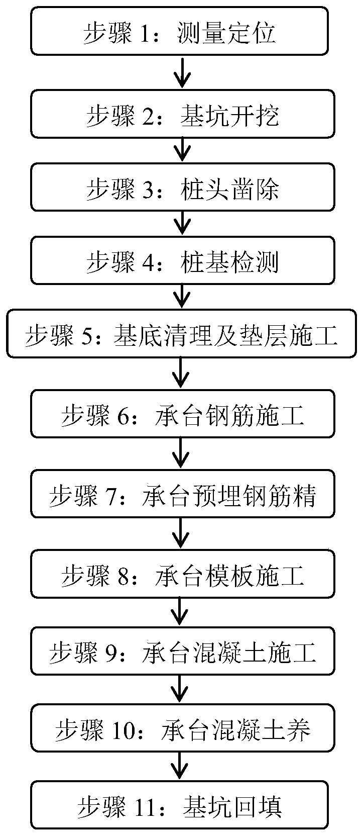
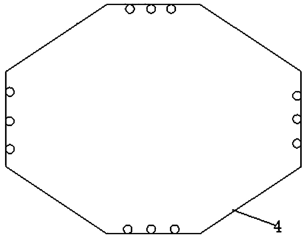
[0033] Such as figure 1 As shown in Figure 3, a construction method for caps within the scope of prefabricated prefabricated columns, the specific implementation process steps are:

[0034] S1: measurement positioning;

[0035] Measurement and positioning requires professional and technical personnel to be responsible for positioning, measuring and setting out work to ensure the accuracy of the location and elevation of the foundation pit. Use total stations and theodolites to measure and position and set the foundation pit elevation control points. After setting the control points, perform foundation pit positioning, and then Excavation of foundation pit earthwork.

[0036] S2: foundation pit excavation;

[0037] The foundation pit of t...


PUM


Abstract

The invention discloses a bearing platform construction process method within a prefabricated vertical column range, and relates to the field of bridge engineering construction. The method includes the following steps of S1, base cleaning and cushion layer construction, wherein a prefabricated vertical column embedded reinforcement cage sideline is positioned and paid off, multiple anchor bolts are evenly distributed on the outer side of the sideline in an embedded manner, and the anchor bolts are poured into a cushion layer; S2, bearing platform rebar construction, wherein an octagonal rebarpositioning device is welded through angle steel, a bound reinforcement cage is hoisted above the rebar positioning device, and the periphery of the embedded reinforcement cage is welded and fixed through cable-stayed rebars; and S3, precision control of bearing platform embedded rebars, wherein the relative positions of the embedded rebars are controlled through limiting formworks on the top faces of the prefabricated vertical column embedded rebars, multiple steel pipes and jacks are used below the limiting formworks for supporting the limiting formworks, and the tail ends of the steel pipesare supported on a steel formwork erected on the outer side of a bearing platform. The construction method has the beneficial effects that the construction process is simple, a construction verticalcolumn is convenient to determine, the stability is good, the economic cost is reduced, and the influence on surrounding environments is low.

Description

technical field [0001] The invention relates to the field of bridge engineering construction, in particular to a construction process method for caps within the scope of prefabricated prefabricated columns. Background technique [0002] At present, in the construction of urban bridges, the cap is the connection part between the pile and the column or pier, and the cap connects several, even dozens of piles together to form a pile foundation. Caps are divided into high pile caps and low pile caps: low pile caps are generally buried or partially buried in the soil, high pile caps are generally exposed to the ground or water surface; high pile caps have a free length, There is no supporting body around it to jointly bear the horizontal external force, and the stress of the foundation pile is extremely unfavorable. The internal force and displacement of the pile body are larger than that of the low pile cap under the same horizontal external force, and its stability is worse tha...

Claims


Application Information

Patent Timeline
IPC IPC(8): E01D19/02E01D21/00
CPCE01D19/02E01D21/00
Inventor 魏志松孔恒王君姜培培王元坤张航李生龙
Owner BEIJING MUNICIPAL CONSTR
Learn More