Eureka AIR delivers breakthrough ideas for toughest innovation challenges, trusted by R&D personnel around the world.

Prefabricated bridge pier steel bar connection manner and construction method thereof

A connection method and steel bar technology, which is applied in bridges, bridge construction, erection/assembly of bridges, etc., can solve the problems of difficult control of expansive mortar expansion, difficult quality assurance, and low tensile capacity, so as to improve tensile capacity and construction Convenient and reliable effect

Pending Publication Date: 2019-11-15
JSTI GRP CO LTD +1
View PDF0 Cites 9 Cited by
  • Summary
  • Abstract
  • Description
  • Claims
  • Application Information

AI Technical Summary

Problems solved by technology

[0004] The purpose of the present invention is to overcome the defects that the expansibility of the expansion mortar in the grouting sleeve in the prefabricated bridge pier is difficult to control, the quality is difficult to guarantee, and the tensile capacity of the sleeve grouting connection is not high in the past, and then provide a prefabricated bridge pier reinforcement connection method and its The construction method, the present invention adopts mechanical connection, the accuracy and quality assurance are better, the tensile capacity of the grouting sleeve is effectively improved, and the construction is reliable and convenient

Method used


Image

  • Prefabricated bridge pier steel bar connection manner and construction method thereof
  • Prefabricated bridge pier steel bar connection manner and construction method thereof
  • Prefabricated bridge pier steel bar connection manner and construction method thereof

Examples


Embodiment Construction

[0021] Below in conjunction with accompanying drawing, the present invention will be further described:

[0022] Such as figure 1 , 2 As shown in , 3, a prefabricated bridge pier steel bar connection method includes a steel bar 1 and a grouting sleeve 2 embedded in a prefabricated concrete member. A grouting hole 4 is provided, a grouting hole 5 is provided at the other end, a limit baffle 6 at the center of the grouting sleeve, and rubber ring plugs 7 at the ports at both ends.

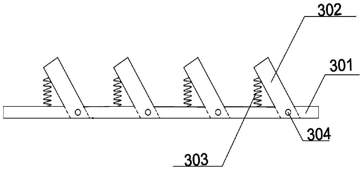
[0023] The steel chisel bar includes a steel backing plate 301, a joint 302, a spring 303 and a steel pivot pin 304. The bottom of the joint 302 and the steel backing plate have small reserved holes, and the steel pin shaft 304 runs through the joint and the steel backing plate. The reserved hole of the steel backing plate, while the other side of the joint 302 is connected with the steel backing plate 301 through the spring 303, the angle formed between the joint 302 and the steel backing plate 30...


PUM


Abstract

The invention discloses a prefabricated bridge pier steel bar connection manner and a construction method thereof. A steel bar embedded in a precast concrete component and a grouting sleeve are included, a steel chisel strip is arranged on the inner wall of the grouting sleeve along the circumference, one end of the grouting sleeve is provided with a grouting hole, the other end of the grouting sleeve is provided with a slurry discharging hole, a limit baffle is arranged at the center of the sleeve, rubber ring plugs are arranged on ports of the two ends, the steel chisel strip is welded to the inner wall of the sleeve, the surface of the steel bar is in a concave-convex shape, and the shape of a joint of the steel chisel strip is matched with the steel bar to form mechanical overlap. In the installation process of a prefabricated bridge pier, after a prefabricated component is straightened and positioned, the other end of the steel bar is inserted into the grouting sleeve, as the joint of the steel chisel strip is in mechanical connection with the steel bar, the steel bar is not easily pulled out, and at the time, ordinary mortar is poured from the grouting hole. According to theprefabricated bridge pier steel bar connection manner and the construction method, the steel bar and the grouting sleeve have mechanical biting force, the steel bar is not easy to be pulled out, certain tensile and compressive resistance can be provided, then the ordinary mortar is poured into the sleeve, and the construction accuracy and quality assurance are better.

Description

technical field [0001] The invention relates to a sleeve grouting connection mode and a construction method in the assembly process of prefabricated bridge piers, and belongs to the field of bridge prefabricated assembly engineering construction. Background technique [0002] With the continuous development of domestic prefabricated bridges, more and more domestic scholars are conducting research on them. However, the core problem of prefabricated bridges is the connection processing method of prefabricated sections. High tensile strength, reliable connection and convenient construction are called the most widely used method of steel bar connection in prefabricated piers. In the past, the sleeve grouting connection was mainly to insert the steel bar into the grouting sleeve from both ends, and then Pour in expansive high-strength mortar to firmly combine the steel bars and sleeves into one. However, the expansibility of the poured expansive high-strength mortar has always b...

Claims


Application Information

Patent Timeline
IPC IPC(8): E01D21/00E04C5/16
CPCE01D21/00E04C5/165
Inventor 张建东熊辉刘朵张金康王建凌伟许炜立
Owner JSTI GRP CO LTD
Why Eureka
Eureka Blog
Learn More