Municipal drainage pipe pit groove supporting structure

A technology of supporting structure and drainage pipe, which is applied in the sewer system, infrastructure engineering, waterway system, etc., can solve the problems of poor practicability, inconvenient use, support and protection, etc., and achieve the effect of wide range of pits

Active Publication Date: 2019-11-15
温州市鹿通建设有限公司
View PDF9 Cites 12 Cited by
  • Summary
  • Abstract
  • Description
  • Claims
  • Application Information

AI Technical Summary

Problems solved by technology

[0004] However, in the actual use of the support row piles in the above-mentioned patents, the height of the support row piles cannot be adjusted because the support row piles are integrated. When the pit is deep, the relatively fixed support row piles will It is difficult to support and protect the pit at the upper end, so there are certain limitations in use. When the depth of the pit of the drainage pipe is different, different types of supporting piles must be used to protect the pit, which is not convenient to use. Less practical

Method used


Image

  • Municipal drainage pipe pit groove supporting structure
  • Municipal drainage pipe pit groove supporting structure
  • Municipal drainage pipe pit groove supporting structure

Examples


Embodiment Construction

[0034] The present invention will be further described with reference to the accompanying drawings.

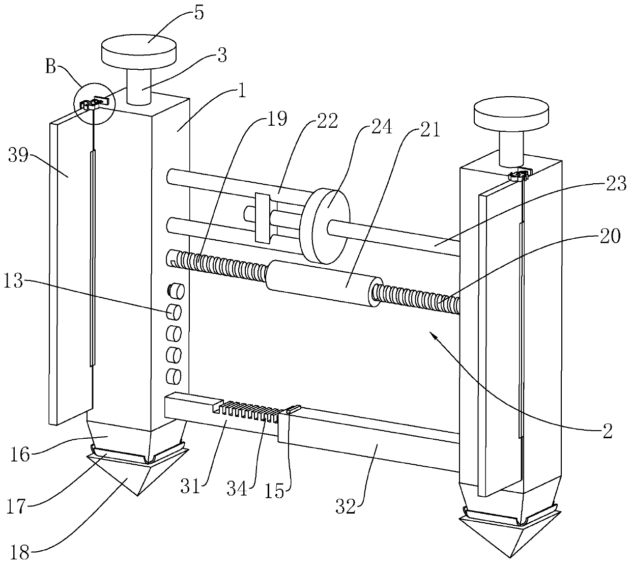
[0035] Such as figure 1 As shown, a municipal drainage pipe pit support structure includes two vertical and opposite support piles 1, and the opposite side walls of the two support piles 1 are respectively fixedly connected with opposite sliding frames 22 and insertion rods. 23. The sliding frame 22 and the insertion rod 23 are horizontally arranged on the upper ends of the two retaining piles 1 .

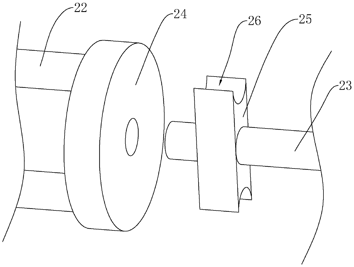
[0036] Such as figure 1 , figure 2 As shown, the sliding frame 22 is fixedly connected with a vertical limit plate 24 toward one end of the insertion rod 23, and the insertion rod 23 is inserted into the sliding frame 22 from the middle part of the limit plate 24, and the insertion rod 23 inserted in the sliding frame 22 The front end is fixedly connected with two card holders 25, and the two card holders 25 are respectively arranged on the side walls of the insertion rods 23 t...


PUM


Abstract

The invention discloses a municipal drainage pipe pit groove supporting structure, and relates to the technical field of pit groove supporting structures. According to the key points of the technicalscheme, the municipal drainage pipe pit groove supporting structure comprises two oppositely-arranged supporting piles, screw rods are rotatably connected into the supporting piles, rotating wheels are fixedly arranged on the screw rods, lifting inserting seats are connected to the screw rods in a threaded mode and slidably arranged in the supporting piles, vertical limiting strips are arranged onthe outer sides of the lifting inserting seats, sliding grooves facing the limiting strips are formed in the supporting piles correspondingly, and the limiting strips are slidably arranged in the sliding grooves; and receding grooves are formed in the limiting strips, inserting blocks are slidably arranged in the receding grooves, compression springs used for jacking the inserting blocks out of the receding grooves are further fixedly arranged in the receding grooves, the other ends of the compression springs are fixedly connected with the inserting blocks, and inserting holes allowing the inserting blocks to penetrate out are formed in the supporting piles correspondingly. The municipal drainage pipe pit groove supporting structure has the effects that the height of the supporting pilescan be adjusted, thus the municipal drainage pipe pit groove supporting structure can be suitable for drainage pipe pit grooves of different depths, and the practicability during using is improved.

Description

technical field [0001] The invention relates to the technical field of pit support structures, more specifically, it relates to a municipal drainage pipe pit support structure. Background technique [0002] Municipal drainage pipes refer to rainwater and sewage pipes under municipal roads, commonly known as "sewer pipes", and are usually called municipal drainage pipes in engineering. According to the current situation of the facilities under the municipal roads in China, different pipelines are generally installed, such as electricity, communication, gas, water supply, drainage pipelines and so on. During the construction of municipal drainage pipelines in cities and towns, problems such as complex engineering geology, small construction area, and short construction period are often encountered. If the construction is carried out according to conventional construction methods, it is difficult to ensure the safety of buildings adjacent to the operation area. [0003] In the...

Claims


Application Information

Patent Timeline
Patent Type & Authority Applications(China)
IPC IPC(8): E02D17/08E03F3/06
CPCE02D17/08E02D17/083E03F3/06
Inventor 黄亮胡晓珍胡志建林思定胡永源
Owner 温州市鹿通建设有限公司
Why Eureka
Try Eureka