Mobile vibration testing device and cable force testing method

A technology of vibration testing and testing methods, which is applied in the directions of measuring devices, tension measuring, force/torque/power measuring instruments, etc., can solve the problems of restricting popularization and application, large human interference factors, etc., and achieve accurate fitting results and high precision Fitting, easy to promote the effect of application

Pending Publication Date: 2019-11-15
GUANGXI UNIV
View PDF0 Cites 1 Cited by
  • Summary
  • Abstract
  • Description
  • Claims
  • Application Information

AI Technical Summary

Problems solved by technology

The layout position of the vibration sensor near the end of the cable needs to be adjusted artificially according to engineering experience, which introduces a large artificial interference factor to the test results of the cable force, which greatly limits the popularization and application of this method

Method used


Image

  • Mobile vibration testing device and cable force testing method
  • Mobile vibration testing device and cable force testing method

Examples


Embodiment 1

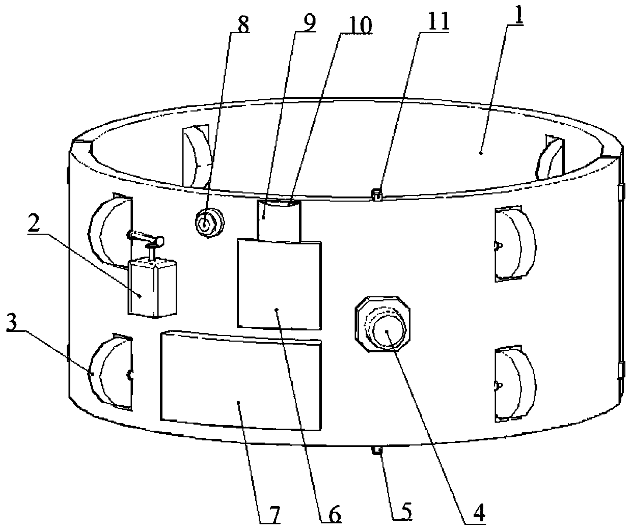
[0047] Such as figure 1 As shown, a mobile vibration testing device includes a cylindrical body 1 , which is a hoop and is composed of two semicircular members, so as to be easily installed on a cable member 12 .

[0048] The body 1 is provided with a running unit, a testing unit, a control unit, a storage unit and a power supply unit.

[0049] The traveling unit includes a motor 2 and a plurality of traveling wheels 3, the motor 2 is connected to the plurality of traveling wheels 3, and the plurality of traveling wheels 3 are arranged symmetrically on the body 1, and the motor 2 is used to drive the The traveling wheel 3 rotates, and the traveling wheel 3 is used to drive the body 1 to travel along the cable member 12 .

[0050] The test unit includes a vibration sensor 4 for collecting vibration signals, such as acceleration, velocity or displacement.

[0051] The control unit is respectively connected with the travel unit, the test unit, and the storage unit, and the cont...

Embodiment 2

[0056] A cable force testing method, comprising the following steps:

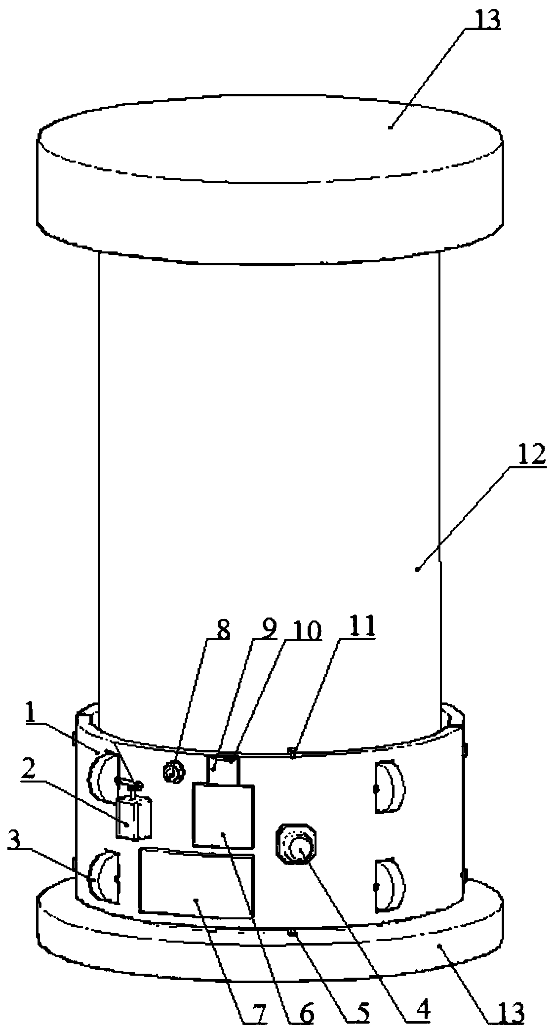
[0057] Step 1: a kind of mobile vibration testing device described in embodiment 1 is installed on one end of cable member 12, as figure 2 shown;

[0058] Step 2: Turn on the power switch 8, the microswitch 1 5 contacts and triggers the cable guide 13, sends an electric signal to the single-chip microcomputer 6, and the single-chip microcomputer 6 starts the running unit, the test unit and the storage unit after receiving the electric signal, and the running wheel 3 drives The main body 1 walks along the cable member 12 to the other end of the cable member 12. During the walking process, the vibration sensor 4 continuously tests the vibration of the cable member 12, and sends the vibration signal to the single-chip microcomputer 6. The single-chip microcomputer 6 will test the time and the collected vibration The signal is sent to the flash memory card 10 for storage;

[0059] When the traveling wheel 3 ...


PUM


Abstract

The invention discloses a mobile vibration testing device and a cable force testing method. The mobile vibration testing device comprises a body, a control unit and a storage unit, wherein a travelingunit and a testing unit are arranged on the body; the traveling unit is used for driving the body to travel; the testing unit comprises a vibration sensor for collecting vibration signals; the control unit is connected with the traveling unit, the testing unit and the storage unit; the control unit is used for controlling the traveling unit, the testing unit and the storage unit; the storage unitis used for storing vibration signals. The cable force testing method comprises the following steps: starting the testing device; driving the body to travel along a cable member by the traveling unit, continuously testing vibration of the cable member by the testing unit in the traveling process and sending the vibration to the control unit; sending the testing time and the vibration signal to the storage unit by the control unit for storage; identifying constraint conditions at two ends of the cable member according to the signals to obtain cable force of the cable member.

Description

technical field [0001] The invention relates to the technical field of cable force testing, in particular to a mobile vibration testing device and a cable force testing method. Background technique [0002] Cable components are commonly used force-bearing components in civil engineering, such as cable-stayed cables in cable-stayed bridges, slings in suspension bridges, suspenders in under-supported arch bridges, and cable domes in buildings. The stress state of the structure is directly related to the safety and reliability of the entire structure, and it is very important to accurately identify the cable force of the cable components. [0003] At present, the test methods for cable force of cable members mainly include hydraulic jack test method, pressure sensor test method, strain sensor test method, magnetic flux sensor test method, vibration sensor test method and so on. However, in the actual application process, each method has certain deficiencies. [0004] (1) Hydr...

Claims


Application Information

Patent Timeline
Patent Type & Authority Applications(China)
IPC IPC(8): G01L5/04
CPCG01L5/042
Inventor 周筱航邓年春谢开仲郭晓曹璐
Owner GUANGXI UNIV
Why Eureka
Try Eureka