Supercharge Your Innovation With Domain-Expert AI Agents!

Display panel and manufacturing method thereof, and display device

A display panel and display area technology, applied in semiconductor/solid-state device manufacturing, semiconductor devices, electrical components, etc., can solve problems such as abnormal display of the display panel, damage to the normal function of the organic light-emitting material layer, and achieve the effect of avoiding failure

Active Publication Date: 2019-11-15
WUHAN TIANMA MICRO ELECTRONICS CO LTD
View PDF9 Cites 7 Cited by
  • Summary
  • Abstract
  • Description
  • Claims
  • Application Information

AI Technical Summary

Problems solved by technology

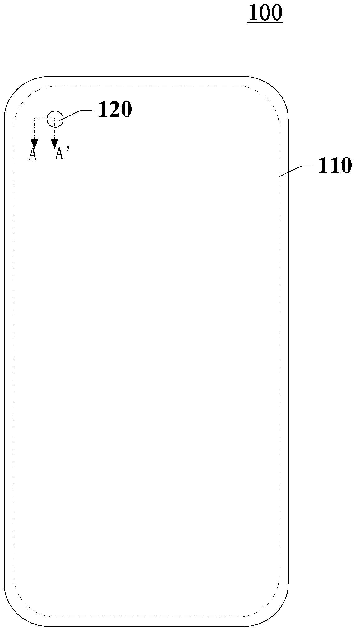
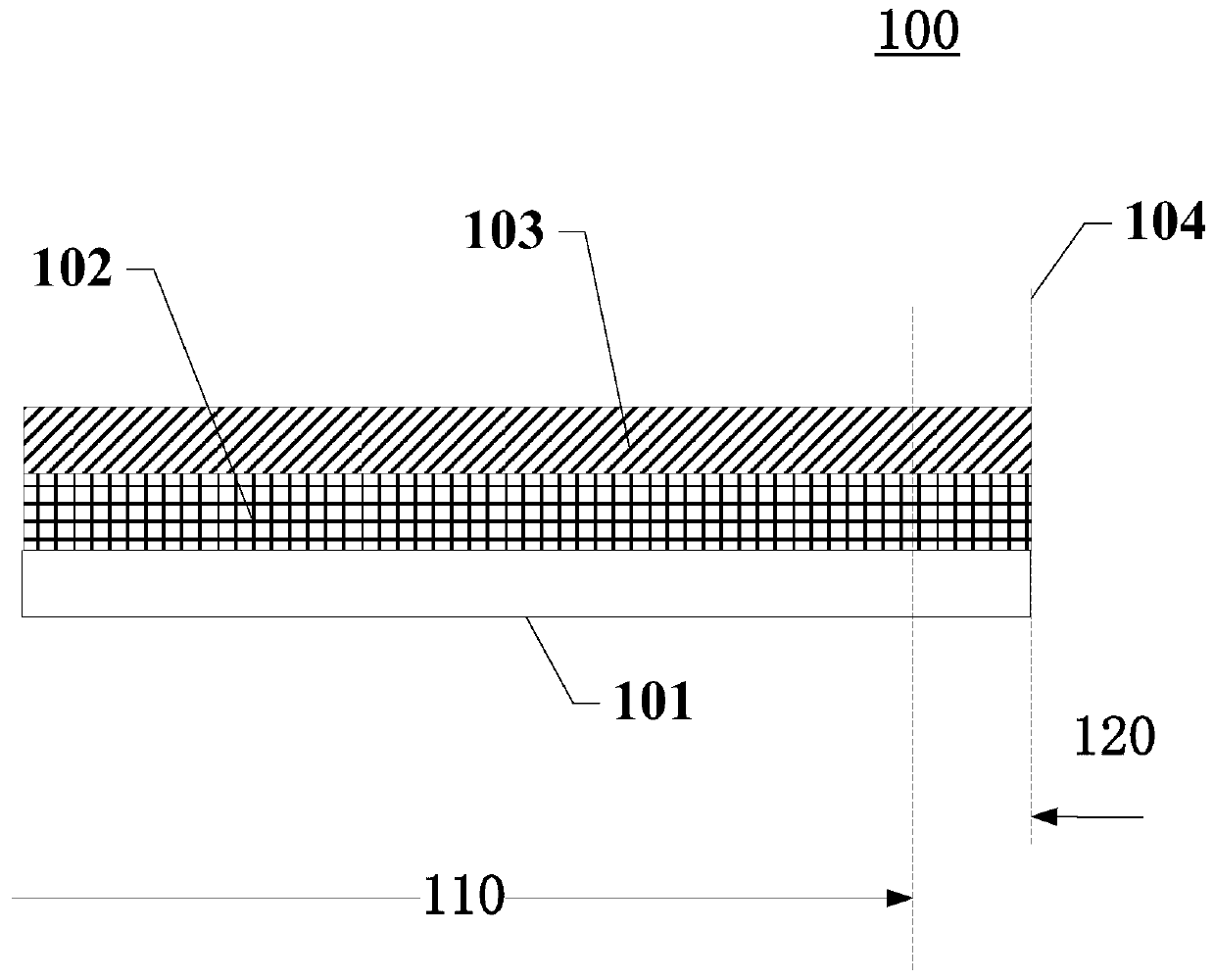
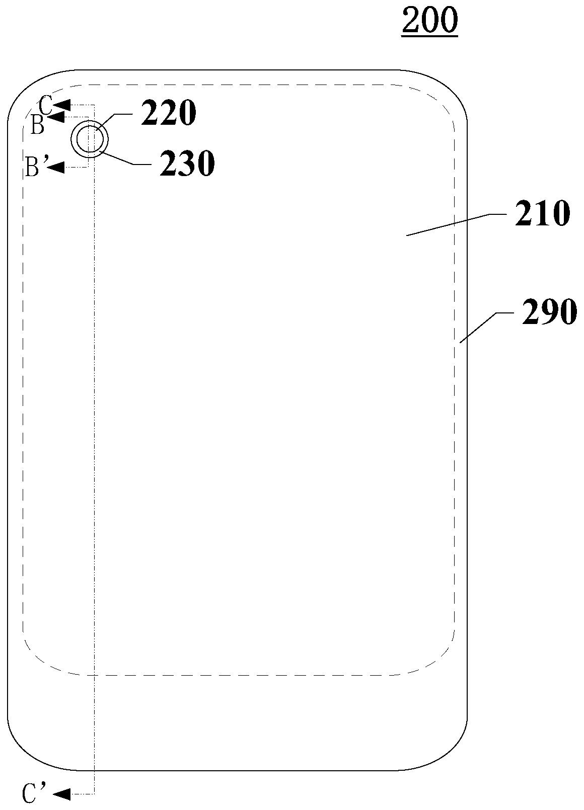
Usually, when making a display panel, the process of evaporating luminescent materials is to vapor-deposit the entire surface of the display area; after completing the basic production of the display panel, dig holes within the limited range of the display area to form through holes for devices such as cameras , the corresponding through hole will penetrate the organic light-emitting material layer, causing the organic light-emitting material layer to be exposed on the inner wall of the through hole, and the external moisture and oxygen can easily spread from the position of the through hole to the display area, and the moisture and oxygen are very likely to destroy the organic light emitting material layer. Normal function of the luminescent material layer, which can cause display anomalies in the entire display panel

Method used


Image

  • Display panel and manufacturing method thereof, and display device
  • Display panel and manufacturing method thereof, and display device
  • Display panel and manufacturing method thereof, and display device

Examples


Embodiment Construction

[0041] Certain terms are used, for example, in the description and claims to refer to particular components. Those skilled in the art should understand that hardware manufacturers may use different terms to refer to the same component. The specification and claims do not use the difference in name as a way to distinguish components, but use the difference in function of components as a criterion for distinguishing. As mentioned throughout the specification and claims, "comprising" is an open term, so it should be interpreted as "including but not limited to". "Approximately" means that within an acceptable error range, those skilled in the art can solve the technical problem within a certain error range and basically achieve the technical effect. The subsequent description of the specification is a preferred implementation mode for implementing the application, but the description is for the purpose of illustrating the general principle of the application, and is not intended...


PUM


Abstract

The invention discloses a display panel and a manufacturing method thereof, and a display device and relates to the technical field of display. The display panel includes a hole region, a first non-display region and a display region and further includes a base substrate, a light emitting device layer and a packaging layer, wherein the light emitting device layer is located on one side of the basesubstrate and includes an anode layer, a light emitting layer and a cathode layer, the packaging layer is located on a side of the light emitting device layer away from the base substrate and includes a first inorganic packaging layer, an organic packaging layer and a second inorganic packaging layer disposed in order, the hole region is at least provided with an organic packaging layer, a firstinorganic packaging layer and a light emitting device layer in a direction perpendicular to the base substrate in a penetration mode, the second inorganic packaging layer covers the boundary of the organic packaging layer, the first inorganic packaging layer and the light emitting device layer at the hole region, and the orthographic projection of the second inorganic packaging layer on the base substrate covers the hole area. The display panel is advantaged in that a problem that the water vapor in the air penetrates from the boundary between the hole area and the first non-display area and spreads to the entire display panel and causes the display panel to fail can be effectively solved.

Description

technical field [0001] The present application relates to the field of display technology, in particular, to a display panel, a manufacturing method thereof, and a display device. Background technique [0002] Common display devices, such as monitors, televisions, mobile phones, tablet computers, etc., usually have a display area that is a regular rectangle, and a plurality of sub-pixels distributed in an array are arranged in the display area. [0003] In recent years, with the development of science and technology, the use of display devices with display panels has become more and more extensive, making people's requirements for display panels more and more diverse, and they are no longer satisfied with large-size, high-definition display panels. Conventional performance indicators such as high temperature also have more diverse requirements for the shape of the display panel, and at the same time have higher requirements for the screen-to-body ratio. [0004] The develop...

Claims


Application Information

Patent Timeline
IPC IPC(8): H01L51/52H01L51/56H01L27/32
CPCH10K59/12H10K50/844H10K71/00
Inventor 蔡雨
Owner WUHAN TIANMA MICRO ELECTRONICS CO LTD
Features
  • R&D
  • Intellectual Property
  • Life Sciences
  • Materials
  • Tech Scout
  • Unparalleled Data Quality
  • Higher Quality Content
  • 60% Fewer Hallucinations
Learn More