
Button battery for improving utilization rate of radial space

A button battery, utilization technology, applied in primary batteries, small-sized batteries/batteries, batteries, etc., can solve the problems of large battery space, unguaranteed quality qualification rate, poor sealing reliability, etc., to improve production. Efficiency, improved utilization, and the effect of qualified rate assurance

Pending Publication Date: 2019-11-15
CHONGQING VDL ELECTRONICS
View PDF1 Cites 32 Cited by
  • Summary
  • Abstract
  • Description
  • Claims
  • Application Information

AI Technical Summary

Problems solved by technology

[0002] The shells of button batteries currently on the market are not integrated designs, and there is a technical problem of poor sealing reliability. For example, a button battery disclosed in application number 201920094848. The sealed sealing ring main body, through the R angle sealing technology of the shell, compresses the sealing ring body in an interference fit manner to realize the sealing function between the positive shell and the negative shell, but the measurement of the R angle by the existing technical means is not very accurate , the good sealing of the battery shell cannot be fully guaranteed, and there is a technical problem that the quality pass rate cannot be guaranteed. At the same time, looking at the circumferential direction of the battery, the outer ring of the battery is the positive shell, the inner ring is the negative shell, the positive shell and the negative shell There is also a sealing ring main body between them. This multi-layer structure occupies too much space in the radial direction of the battery, and there is a technical problem that the radial space cannot be fully utilized.

Method used


Image

  • Button battery for improving utilization rate of radial space
  • Button battery for improving utilization rate of radial space
  • Button battery for improving utilization rate of radial space

Examples


Embodiment Construction

[0027] In order to make the purpose, technical solutions and advantages of the embodiments of the present invention clearer, the technical solutions in the embodiments of the present invention will be clearly and completely described below in conjunction with the drawings in the embodiments of the present invention. Obviously, the described embodiments It is a part of embodiments of the present invention, but not all embodiments. Based on the embodiments of the present invention, all other embodiments obtained by persons of ordinary skill in the art without creative efforts fall within the protection scope of the present invention.

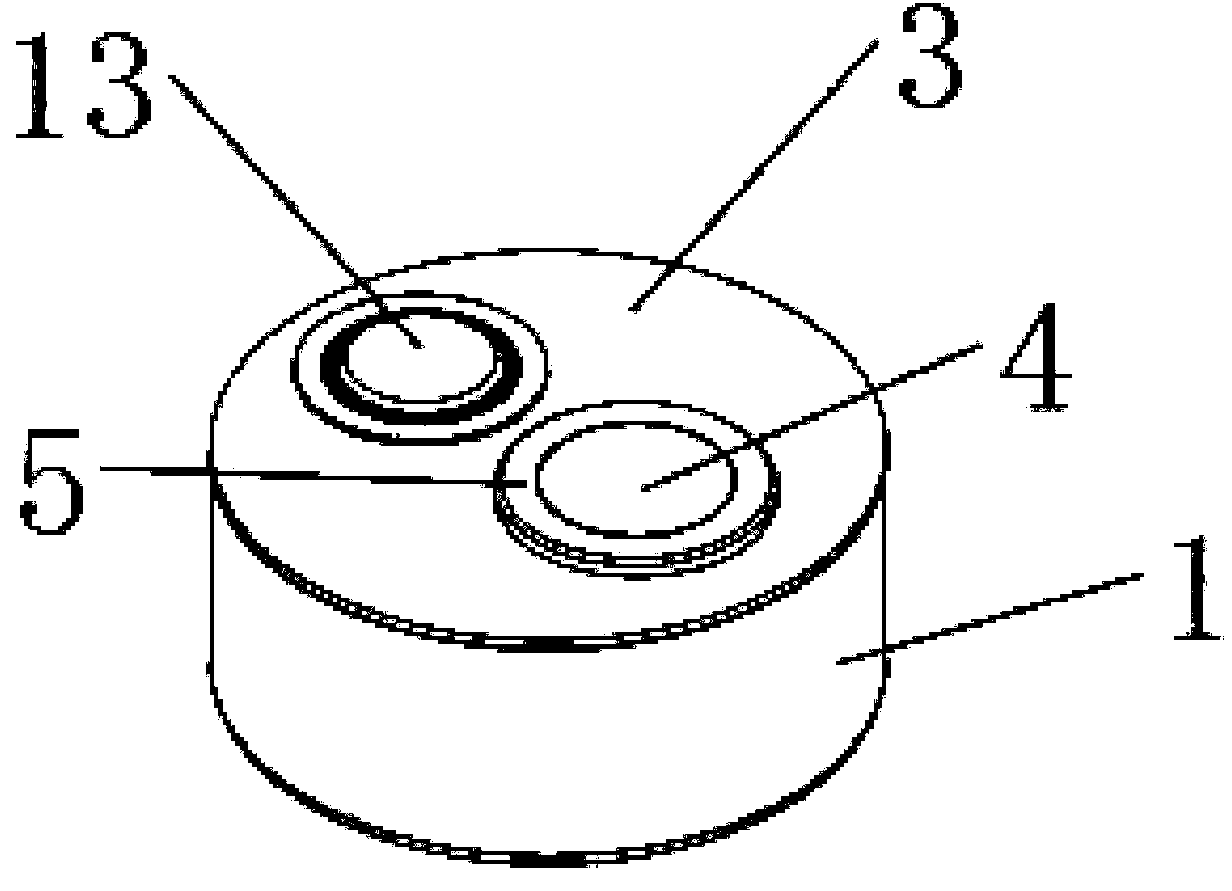
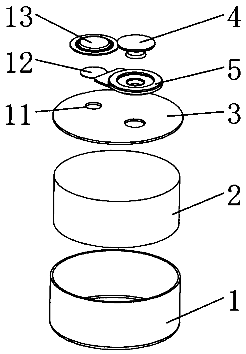
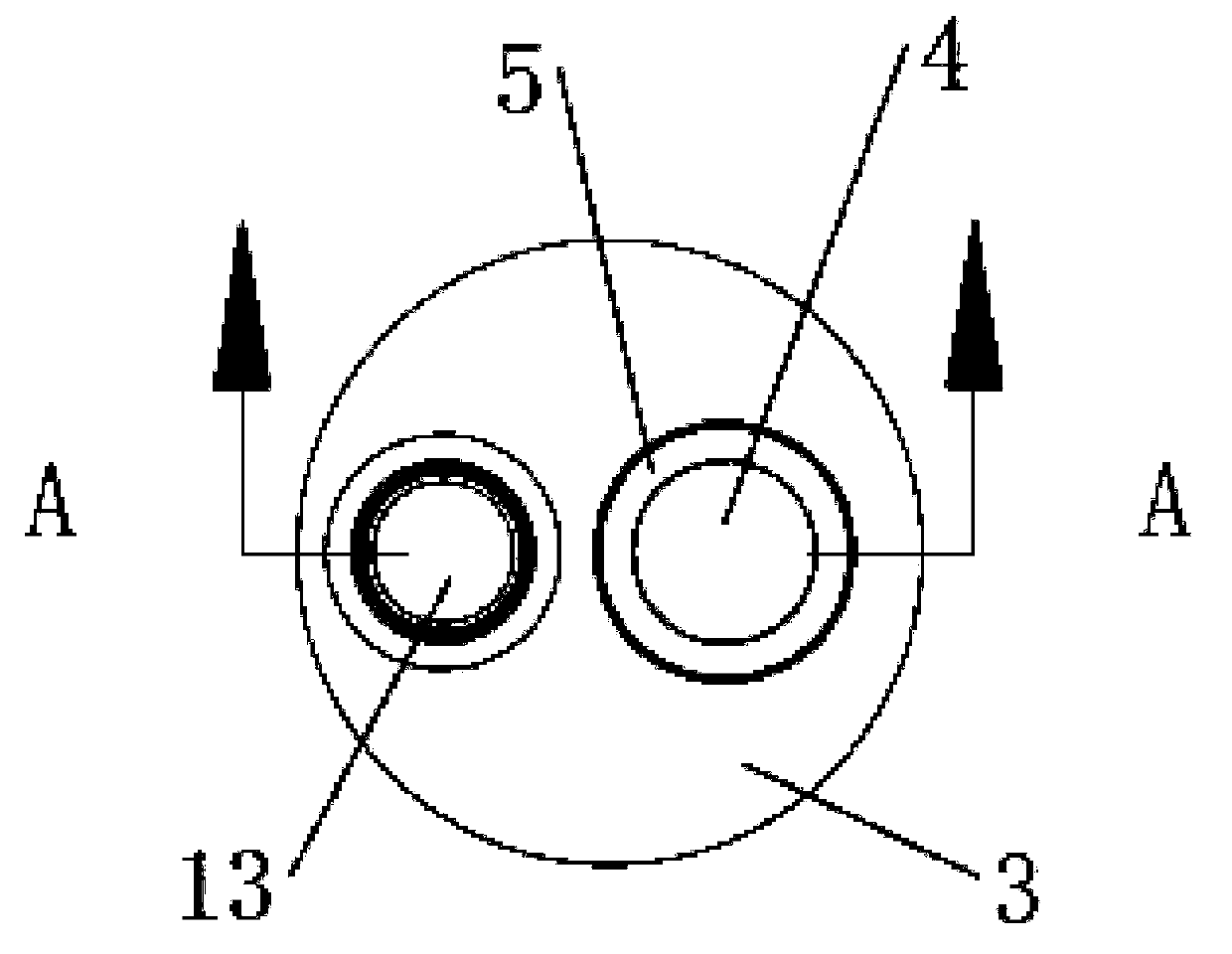
[0028] like Figure 1-Figure 5 As shown, the present invention provides a kind of button cell that promotes radial space utilization ratio, comprises metal case 1, and described metal case 1 is the cylindrical shape of upper end opening, and the ratio of diameter and height of described cylindrical metal case 1 is greater than 1. The metal casing...


PUM

PropertyMeasurementUnit
thicknessaaaaaaaaaa

Abstract

The invention discloses a button battery for improving the utilization rate of radial space, which comprises a metal housing and an electric core arranged in the metal housing, wherein the electric core comprises a positive plate and a negative plate. The button battery further comprises a cover plate arranged on the metal housing, wherein the cover plate and the metal housing have the same polarity, and the cover plate and the metal housing are welded into a whole by laser, so that the sealing property of the battery housing is more reliable. The outer side of the cover plate is provided witha convex cap, the cover plate and the cap are provided with an insulating piece therebetween which prevents a short circuit between the cover plate and the cap, one of the positive plate and the negative plate is electrically connected with the metal housing or the cover plate, the other of the positive plate and the negative plate is electrically connected with the cap, and the electric core andthe outside are only separated by the single-layer metal housing, so that the utilization rate of the radial space of the battery is improved. Meanwhile, the process of the button battery is simpler,the requirement of full-automatic production of the battery is met, the production efficiency of the battery is improved, and the qualification rate is also well guaranteed.

Description

technical field [0001] The invention relates to the field of button batteries, in particular to a button battery that improves radial space utilization. Background technique [0002] The shells of button batteries currently on the market are not integrated designs, and there is a technical problem of poor sealing reliability. For example, a button battery disclosed in application number 201920094848. The sealed sealing ring main body, through the R angle sealing technology of the shell, compresses the sealing ring body in an interference fit manner to realize the sealing function between the positive shell and the negative shell, but the measurement of the R angle by the existing technical means is not very accurate , the good sealing of the battery shell cannot be fully guaranteed, and there is a technical problem that the quality pass rate cannot be guaranteed. At the same time, looking at the circumferential direction of the battery, the outer ring of the battery is the p...

Claims


Application Information

Patent Timeline
Patent Type & Authority Applications(China)
IPC IPC(8): H01M2/02H01M2/04H01M2/08H01M10/04H01M6/00
CPCH01M10/0427H01M6/00H01M50/109H01M50/169H01M50/153H01M50/183Y02E60/10H01M50/181H01M50/188H01M50/531H01M50/159H01M50/119H01M50/446H01M50/3425Y02P70/50H01M50/172H01M50/543H01M50/528H01M50/60H01M50/636H01M10/0431H01M2200/20
Inventor 周显茂
Owner CHONGQING VDL ELECTRONICS
Learn More