Bridge pile foundation on-site-binding reinforcement cage deviation control formwork and construction method thereof

A technology for reinforcing cages and binding steel bars, which is applied in foundation structure engineering, sheet pile walls, buildings, etc., which can solve the problems of insufficient thickness of steel bar protection layer in pile foundations, affect the internal quality of pile foundations, and high cost, etc., and achieve low production and use costs , simple structure and low cost of use

Pending Publication Date: 2019-11-19
NO 1 ENG CO LTD OF FHEC OF CCCC
View PDF0 Cites 6 Cited by
  • Summary
  • Abstract
  • Description
  • Claims
  • Application Information

AI Technical Summary

Problems solved by technology

[0003] If the deviation of the reinforcement cage of the pile foundation is light, the thickness of the protective layer of the pile foundation reinforcement will be insufficient, and if it is severe, the phenomenon of exposed reinforcement will appear, which will seriously affect the internal quality of the pile foundation
The corrosion of reinforced steel bars caused by the deviation of steel cages and exposed bars is often encountered in the maintenance and reinforcement construction of some bridge pile foundations, and some are quite serious. Since pile foundations are mostly underground or high-altitude projects, it is difficult and time-consuming to deal with them. Labor-intensive and expensive

Method used


Image

  • Bridge pile foundation on-site-binding reinforcement cage deviation control formwork and construction method thereof
  • Bridge pile foundation on-site-binding reinforcement cage deviation control formwork and construction method thereof
  • Bridge pile foundation on-site-binding reinforcement cage deviation control formwork and construction method thereof

Examples


Embodiment 1

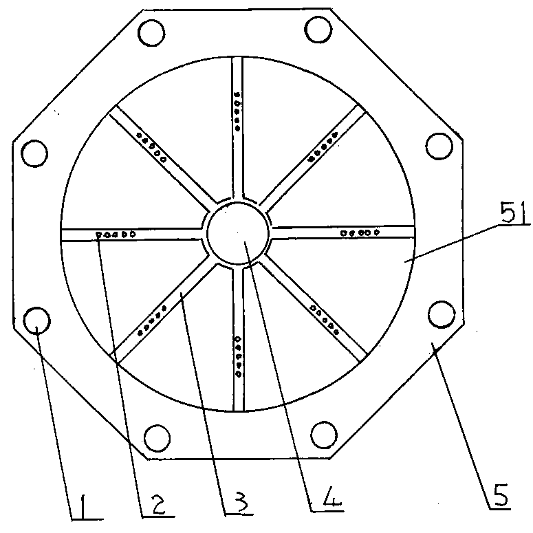
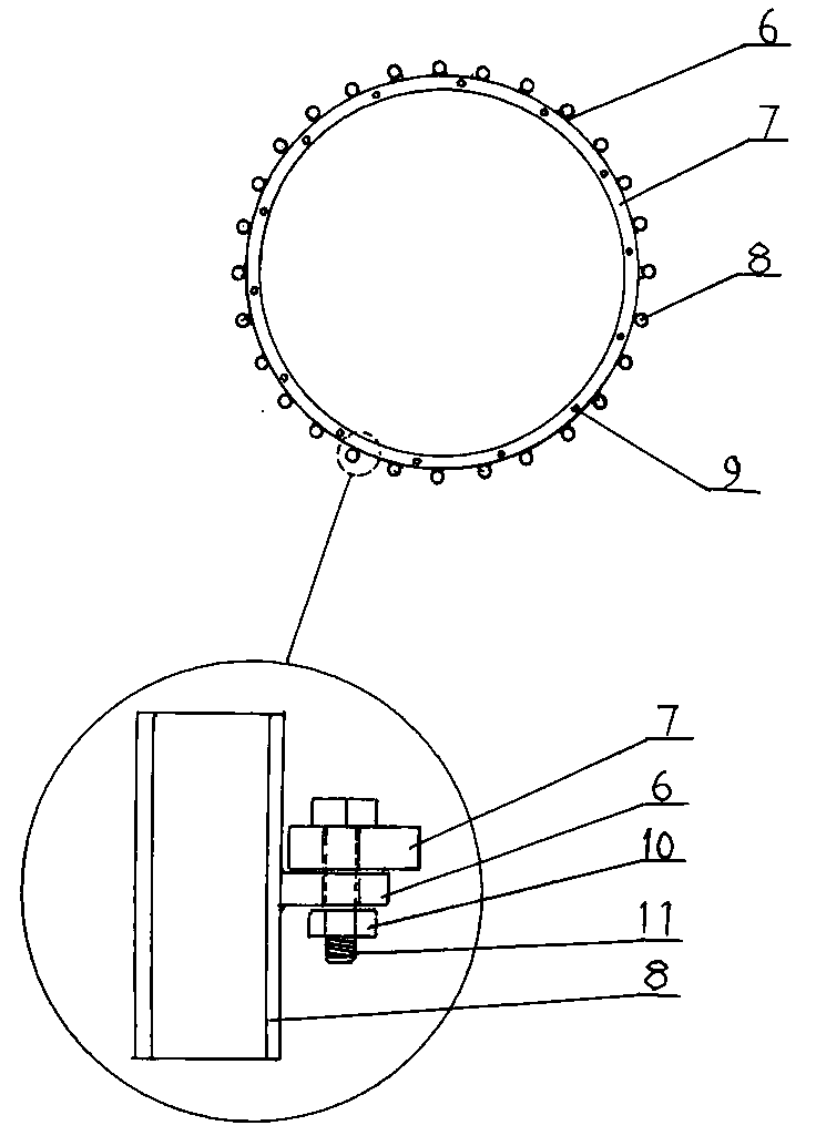
[0053] Embodiment 1: as Figure 1 to Figure 8 As shown, a bridge pile foundation is now bound steel cage deviation control formwork is composed of steel casing 8, wherein:

[0054] Fixed disk panel 5: used to support the fixed disk support frame. The fixed plate panel can be assembled and welded by 6-10mm thick steel plates. The periphery of the fixed plate panel is octagonal, and the diagonal length of the fixed plate panel is 2.75m. A pile foundation through hole 51 is provided in the middle of the fixed disk panel, the diameter of the inner circle is 2.0m, and the diameter of the pile foundation through hole is larger than the diameter of the bridge pile foundation. The opposite corner of the fixed plate panel is provided with a fixed through hole 1, and the fixed through hole is used to fix the fixed plate panel on the upper end of the steel cage construction surface of the bridge pile foundation, that is, the fixed plate panel can be fixed on the fixed through hole with ...

Embodiment 2

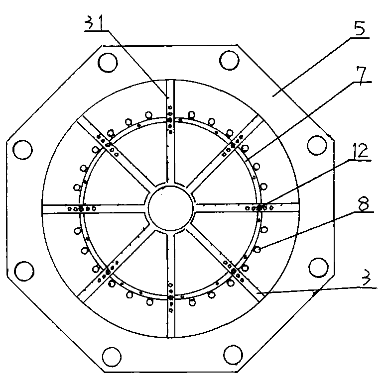
[0081] Embodiment 2: Different from Embodiment 1: if the steel cage bottom diameter size required by the design in the column to be constructed or in the pier is different from the top diameter size (such as a narrow column, pier, etc. on the bottom width), The construction of fixed steel cage positioning plate and steel cage positioning arc plate: then:

[0082] (1) The fixed reinforcement cage positioning plate is selected and placed at the bottom of the pouring formwork in the column or pier. The steel cage positioning arc plate is used to position and fix the steel casing assembly after assembly. Several steel cage positioning arc plates are connected end-to-end with each other, or the two ends of each other are staggered and connected to one side of the fixed plate support frame to form a diameter variable. In the circular annular body, the length of a reinforcement cage positioning arc plate is greater than the distance between two adjacent fixed disk support frames.

...

Embodiment 3

[0090] Embodiment 3: The difference from Embodiments 1 and 2 is that the positioning arc plates of the reinforcement cage and the positioning discs of the moving reinforcement cage can replace each other. At that time, it is only necessary to select and install the mobile reinforcement cage positioning plate corresponding to the same diameter as the reduction reinforcement cage in the diameter reduction reinforcement cage section; and correct the reinforcement sleeve on it to match the longitudinal reinforcement position of the reduction diameter reinforcement cage. So I won't repeat it any more.

[0091] In a word, the present invention can effectively control the correction and apply to the deflection of existing steel cages with different diameters of pile foundations, and has the advantages of simple structure, fast construction speed, good quality, low production and use cost, time-saving and labor-saving, and wide applicability.


PUM


Abstract

The invention belongs to a bridge pile foundation on-site-binding reinforcement cage deviation control formwork and a construction method thereof. The bridge pile foundation on-site-binding reinforcement cage deviation control formwork includes a fixed plate panel, a fixed plate supporting frame, a fixed reinforcement cage positioning plate, a mobile reinforcement cage positioning plate, a reinforcement cage positioning arc plate and a reinforcement sleeve assembly. The construction method includes the steps that the bottom of the on-site-binding reinforcement cage in a column is fixed by thefixed reinforcement cage positioning plate and reinforcement sleeves, the top of the on-site-binding reinforcement cage in the column is fixed by the mobile reinforcement cage positioning plate and the reinforcement cage positioning arc plate and reinforcement sleeves, and construction of various column bodies with different diameters is completed by changing the diameters of the mobile reinforcement cage positioning plate and the reinforcement cage positioning arc plate, and the positions of the reinforcement sleeves corresponding to the diameter of the variable diameter reinforcement cage. The bridge pile foundation on-site-binding reinforcement cage deviation control formwork can effectively control, correct and is suitable for the deviation of the on-site-binding reinforcement cage ofpile foundations with different diameters and has the advantages of simple structure, high construction speed, good quality, low production and use cost, less time and labor, and wide applicability.

Description

technical field [0001] The invention belongs to a bridge pile foundation existing binding steel cage deviation control formwork and a construction method thereof. Background technique [0002] The displacement problem of the steel cage of the pile foundation (including bridge piers and columns) is a quality problem often encountered in the construction of the pile foundation, especially the displacement problem of the reinforced cage currently bound in the pile foundation formwork is more serious. In particular, the deflection problem of bridge piers, columns whose diameter is continuously shrinking from the bottom to the top and the width of the bottom and the top is narrow, and the variable-diameter reinforcement cages in the columns are also more serious. [0003] If the deviation of the reinforcement cage of the pile foundation is light, the thickness of the protective layer of the pile foundation reinforcement will be insufficient, and if it is serious, the phenomenon o...

Claims


Application Information

Patent Timeline
Patent Type & Authority Applications(China)
IPC IPC(8): E02D5/34
CPCE02D5/34
Inventor 张达强姚大伟乔刚徐长鑫赵明明佟岩陈治炳王旭江
Owner NO 1 ENG CO LTD OF FHEC OF CCCC
Why Eureka
Try Eureka