A kind of building movable window frame safety device

A technology for safety devices and buildings, applied in building structures, buildings, building components, etc., can solve problems such as connecting rod or connecting position fracture, sliding window fatigue damage, pedestrian safety hazards, etc., to achieve low renovation costs and avoid high altitudes. The effect of falling objects and preventing illegal persons from entering

Active Publication Date: 2020-11-10
浙江皓睿建设有限公司
View PDF6 Cites 0 Cited by
  • Summary
  • Abstract
  • Description
  • Claims
  • Application Information

AI Technical Summary

Problems solved by technology

[0002] The window is composed of a window frame and a movable window frame. The movable window frame mainly includes a sliding window and a sliding window. Every time a sliding window is pushed out, a large force is required. Therefore, after a long period of use, the connecting rod of the sliding window Fatigue damage will occur at the position, which leads to the breakage of the connecting rod or the connection position after the window is used for a long time, causing the movable window frame to fall, causing a greater safety hazard to the pedestrians below

Method used


Image

  • A kind of building movable window frame safety device
  • A kind of building movable window frame safety device
  • A kind of building movable window frame safety device

Examples


Embodiment 1

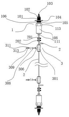
[0042] refer to Figure 1-Figure 6 The shown safety device for a movable window frame of a building comprises two fixing parts 1, upper and lower, and a cable 2 assembled between the two fixing parts 1, and is movably assembled on the cable 2. insurance company 3;

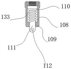
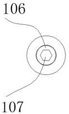
[0043]Described fixture 1 comprises a screw 101, and this screw 101 has self-tapping thread 102, and one end of described screw 101 is processed into sharp end 103, and self-tapping thread 102 extends on this sharp end 103, and the outer wall of described screw 101 A baffle plate 104 for limiting is formed after machining at the place. The other end of the screw 101 is processed with a connecting portion 105. The outside of the connecting portion 105 is processed with a connecting thread 106. A polygonal receiving portion is processed on the end surface of the connecting portion 105. The force hole 107 is equipped with a sleeve 108 through the connecting portion 105, and the end of the sleeve 108 away from the con...

Embodiment 2

[0048] refer to Figure 7 As shown, a pressing piece 331 is screwed into the upper and lower ends of the sliding tube 301, and the pressing piece 331 is screwed in to resist the locking piece 303, and the inner diameter of the pressing piece 331 is larger than the The inner diameter of the locking member 303, when the cable 2 passes through the sliding tube 301, a gap is formed between the cable 2 and the locking member 303; the use of the pressing member is mainly to prevent the sliding tube from sliding When the locking part is separated from the slide tube, the effect of protecting the locking part is achieved.

Embodiment 3

[0050] refer to Figure 8 As shown, two rubber protective sleeves 333 are sleeved on the outer wall of the sliding tube 301. When the sliding window is active, there is a possibility of contact with the sliding tube. Therefore, we have designed a rubber protective sleeve that can be used with the sliding window Soft contact between windows to avoid damage to sliding windows.


PUM


Abstract

The invention discloses a safety device for a movable window frame of a building. The safety device comprises an upper fixing piece, a lower fixing piece, a rope assembled between the two fixing pieces, and a safety mechanism movably assembled on the rope. Each fixing piece comprises a screw provided with a self-tapped thread, wherein one end of the screw is machined into a sharp end, the self-tapped thread extends to the sharp end, the outer wall of the screw is machined to form a baffle used for limiting, a connecting part is machined at the other end of the screw, and a connecting thread ismachined outside the connecting part. The safety device is of an external structure and thus can be used for transforming a mounted window, and the transformation cost is low.

Description

technical field [0001] The invention relates to a safety device for a movable window frame of a building. Background technique [0002] The window is composed of a window frame and a movable window frame. The movable window frame mainly includes a sliding window and a sliding window. Every time a sliding window is pushed out, a large force is required. Therefore, after a long period of use, the connecting rod of the sliding window Fatigue damage will occur at the position, which leads to the breakage of the connecting rod or the connection position after the window is used for a long time, causing the movable window frame to fall, causing a greater safety hazard to the pedestrians below . [0003] For example, in 2019, Xiaohang, a 5-year-old boy in Shenzhen, was walking with his mother on the way to kindergarten, talking and laughing. Suddenly, a catastrophe struck. A whole piece of glass fell from the sky and knocked down the child. Blood flowed all over the ground. The m...

Claims


Application Information

Patent Timeline
Patent Type & Authority Patents(China)
IPC IPC(8): E06B7/28E05F7/00
CPCE05F7/00E05Y2900/148E06B7/28
Inventor 严海良王庆军
Owner 浙江皓睿建设有限公司
Why Eureka
Try Eureka