Prime lens

A fixed-focus lens and lens technology, applied in the field of fixed-focus lenses, can solve problems such as poor imaging quality, achieve the effects of improving efficiency, increasing the proportion of back focus, and reducing production costs

Pending Publication Date: 2019-11-19
舜宇光学(中山)有限公司
View PDF0 Cites 5 Cited by
  • Summary
  • Abstract
  • Description
  • Claims
  • Application Information

AI Technical Summary

Problems solved by technology

[0003] The purpose of the present invention is to provide a fixed focus lens to solve the problem of poor imaging quality

Method used


Image

  • Prime lens
  • Prime lens
  • Prime lens

Examples


Embodiment 1

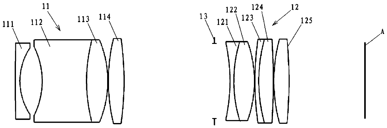
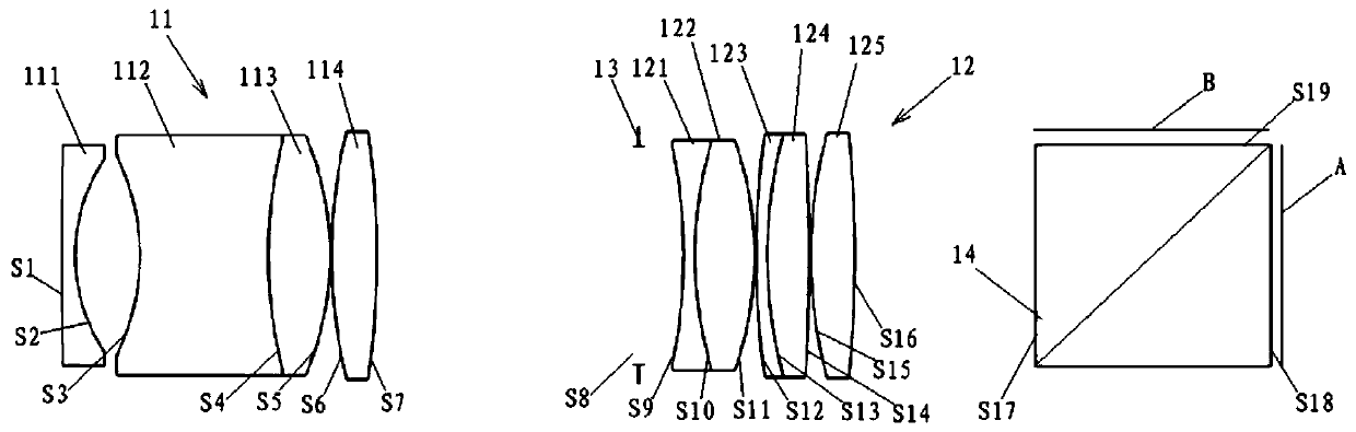
[0064] based on figure 2 The structure of the fixed-focus lens shown is illustrative of this embodiment. see figure 2 As shown, for the convenience of describing the embodiments of the present invention, the mirror surfaces of the fixed-focus lenses of the present invention are numbered from the object side to the image side. therefore. S1 is the object side of the first lens 111 close to the object side, S2 is the image side of the first lens 111 close to the image side; S3 is the object side of the second lens 112 close to the object side, and S4 is the second lens 112 and the third lens 113 S5 is the image side of the third lens 113 close to the image side; S6 is the object side of the fourth lens 114 close to the object side, S7 is the image side of the fourth lens 114 close to the image side; S8 is the diaphragm; S9 is The fifth lens 121 is near the object side of the object side, S10 is the cemented surface of the fifth lens 121 and the sixth lens 122, S11 is the im...

Embodiment 2

[0076] based on Figure 5 The structure of the fixed-focus lens shown is illustrative of this embodiment. see Figure 5As shown, for the convenience of describing the embodiments of the present invention, the mirror surfaces of the fixed-focus lenses of the present invention are numbered from the object side to the image side. therefore. S1 is the object side of the first lens 111 near the object side, S2 is the image side of the first lens 111 near the image side; S3 is the object side of the second lens 112 near the object side, and S4 is the image of the second lens 112 near the image side Side; S5 is the object side of the third lens 113 close to the object side, S6 is the image side of the third lens 113 close to the image side; S7 is the object side of the fourth lens 114 close to the object side, and S8 is the fourth lens 114 close to the image side S9 is the diaphragm; S10 is the object side of the fifth lens 121 near the object side, S11 is the image side of the fi...

Embodiment 3

[0088] based on Figure 8 The structure of the fixed-focus lens shown is illustrative of this embodiment. see Figure 8 As shown, for the convenience of describing the embodiments of the present invention, the mirror surfaces of the fixed-focus lenses of the present invention are numbered from the object side to the image side. therefore. S1 is the object side of the first lens 111 close to the object side, S2 is the image side of the first lens 111 close to the image side; S3 is the object side of the second lens 112 close to the object side, and S4 is the second lens 112 and the third lens 113 S5 is the image side of the third lens 113 close to the image side; S6 is the object side of the fourth lens 114 close to the object side, S7 is the image side of the fourth lens 114 close to the image side; S8 is the diaphragm; S9 is The object side of the fifth lens 121 close to the object side, S10 is the image side of the fifth lens 121 close to the image side; S11 is the object...


PUM


Abstract

The invention relates to a prime lens, which comprises a first lens group (11) and a second lens group (12) sequentially arranged from an object side to an image side. In the direction from the objectside to the image side, the first lens group (11) comprises a first lens (111) with negative focal power, a second lens (112) with negative focal power, a third lens (113) with positive focal power and a fourth lens (114) with positive focal power. In the direction from the object side to the image side, the second lens group (12) comprises a fifth lens (121) with negative focal power, a sixth lens (122) with positive focal power, a seventh lens (123) with negative focal power, an eighth lens (124) with positive focal power, and a ninth lens (125) with positive focal power. According to the prime lens, the lenses meet the matching of the focal power, so that the prime lens has the capability of synchronously imaging visible and near infrared spectrums and can have an ultra-long back focalratio.

Description

technical field [0001] The invention relates to the field of optics, in particular to a fixed-focus lens. Background technique [0002] At present, infrared and visible light confocal lenses generally have such shortcomings: low lens pixels, high and low temperature virtual focus, and high noise in low-light environments. Moreover, most of the existing infrared-visible light confocal lenses need to use a number of high-priced abnormal dispersion and high-refractive index material lenses to achieve clear imaging on the confocal plane in order to overcome the above-mentioned shortcomings. This kind of lens is not only difficult to design and high in development cost, but also difficult to image infrared and visible light with optimal resolution at the same time. Contents of the invention [0003] The object of the present invention is to provide a fixed-focus lens to solve the problem of poor imaging quality. [0004] In order to achieve the purpose of the above invention,...

Claims


Application Information

Patent Timeline
Patent Type & Authority Applications(China)
IPC IPC(8): G02B13/14G02B13/00
CPCG02B13/0015G02B13/005G02B13/008G02B13/146
Inventor 聂路鑫帅皇南翟林燕梁伟朝邹文镔
Owner 舜宇光学(中山)有限公司
Why Eureka
Try Eureka