
Die bonding device for processing music chip of music player and using method thereof

A music player and music chip technology, which is applied in the direction of surface coating devices, semiconductor devices, semiconductor/solid-state device manufacturing, etc. Problems such as insufficient uniformity and comprehensive application, to achieve the effect of high-efficiency solidification work, high degree of automation, and improved efficiency

Active Publication Date: 2019-11-19
YANTAI VOCATIONAL COLLEGE
View PDF7 Cites 4 Cited by
  • Summary
  • Abstract
  • Description
  • Claims
  • Application Information

AI Technical Summary

Problems solved by technology

[0004] The purpose of the present invention is to solve the problem that the existing crystal-bonding device for music chip processing has a low degree of automation in use, and the efficiency of the crystal-bonding work is slow, and after the crystal-bonding device fixes the wafer on the music chip, the crystal-bonding glue The connection between the music chip and the chip is not coated evenly and comprehensively, resulting in an unstable connection between the music chip and the chip, and it is not conducive to the post-welding process of the music chip and the chip, and the die-bonding device drips during the die-bonding work. Glue cannot be collected and recycled in a unified way, and the environmental protection of the use is poor, and a crystal-bonding device for music chip processing of a music player and its use method are proposed

Method used


Image

  • Die bonding device for processing music chip of music player and using method thereof
  • Die bonding device for processing music chip of music player and using method thereof
  • Die bonding device for processing music chip of music player and using method thereof

Examples


Embodiment Construction

[0047] The technical solutions of the present invention will be clearly and completely described below in conjunction with the embodiments. Apparently, the described embodiments are only some of the embodiments of the present invention, not all of them. Based on the embodiments of the present invention, all other embodiments obtained by persons of ordinary skill in the art without creative efforts fall within the protection scope of the present invention.

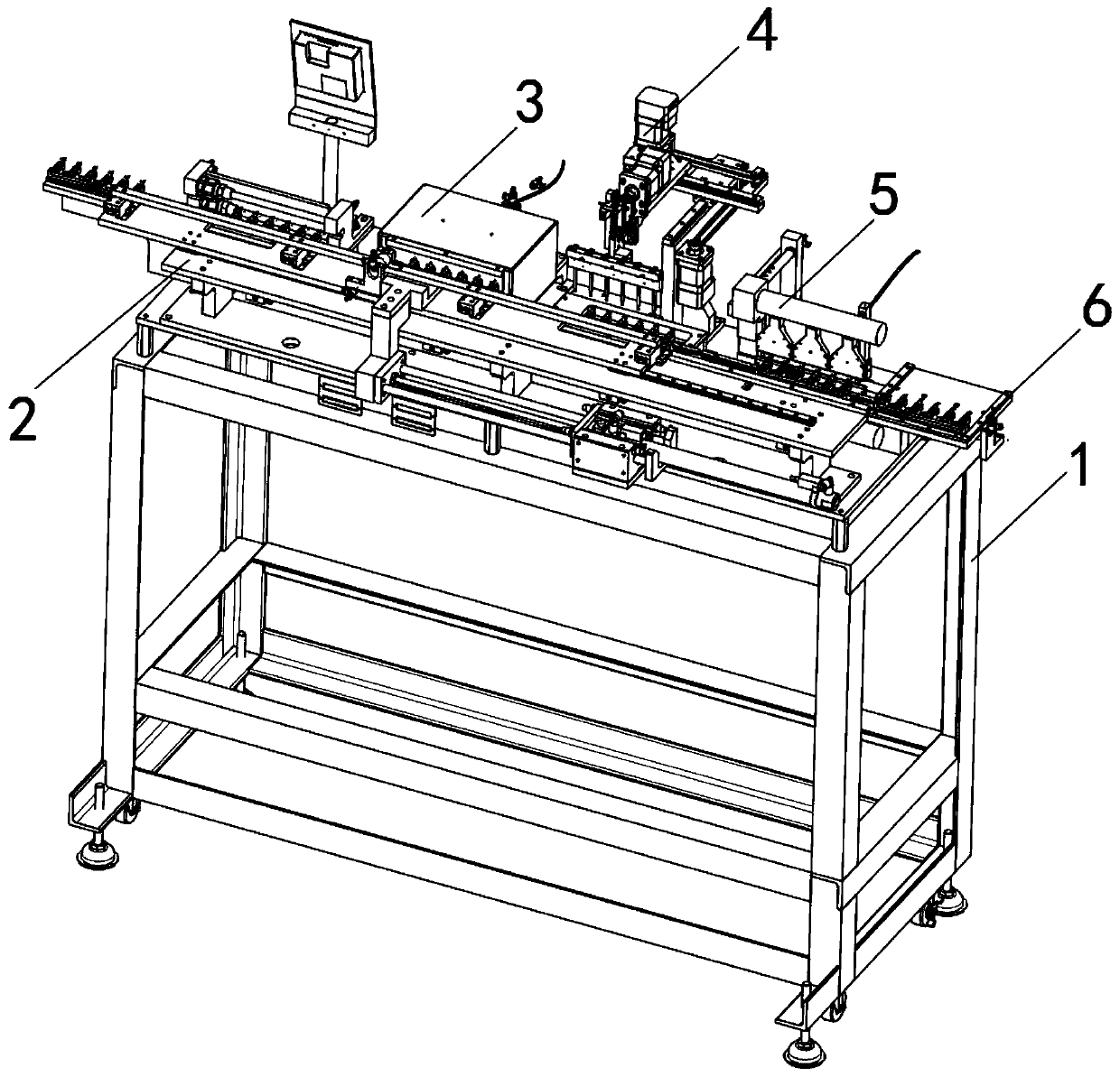
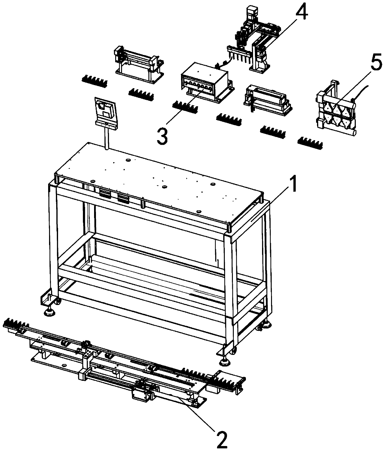
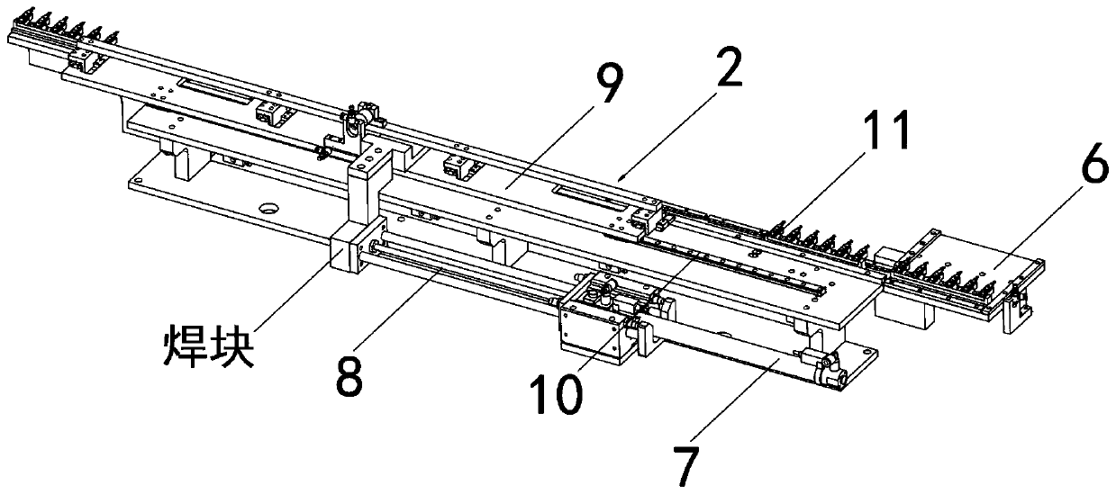
[0048] see Figure 1-13 As shown, a crystal-bonding device for music chip processing of a music player includes a support table 1, a transmission plate 2, a crystal-bonding box 3, a gluing table 4 and a crystal pressing seat 5, and a transmission plate is set on the upper side of the support table 1 2. A cuboid-shaped crystal-fixing box 3 is provided on one side of the transmission disc 2, and a glue-applying table 4 is provided on one side of the crystal-fixing box 3, and a crystal-pressing seat 5 is provided on one side o...


PUM


Abstract

The invention discloses a die bonding device for processing a music chip of a music player and a using method thereof. The die bonding device comprises a supporting table, a transmission disc, a die bonding box, a glue smearing table and a die pressing seat, the transmission disc is arranged on one side of the upper portion of the supporting table, the cuboid die bonding box is arranged on one side of the transmission disc, the glue smearing table is arranged on one side of the die bonding box, and the die pressing seat is arranged on one side of the glue smearing table. The beneficial effectsof the invention are that: the music chips and the wafers on the plurality of mounting blocks are respectively coated with dot die bonding glue through the dispensing nozzles on the plurality of glueoutlet pumps to improve the die bonding efficiency of the music chips by the device; and when the dispensing nozzles are used for dispensing the die bonding glue, the motor I drives the chips and thewafers in the plurality of buckling frames to continuously and slowly rotate through a rotary mounting block, so that the position of the device for dispensing the die bonding glue is more comprehensive, the automation degree of the device is higher while the die bonding work of the device is more efficient, and the device is very time-saving and labor-saving to use.

Description

technical field [0001] The invention relates to a crystal-bonding device, in particular to a crystal-bonding device for processing a music chip of a music player and a method for using the same, belonging to the technical field of crystal-bonding devices. Background technique [0002] When the music chip in the music player is being processed, a die-bonding device is often required to fix the LED chip to the music chip for die-bonding processing, so as to ensure that the soldering and fixing position of the LED chip on the music chip is more accurate in the subsequent processing procedure. , Suitable, when the music chip is working, the LED chip will light up, which improves the audio-visual effect. [0003] The existing crystal-bonding device for music chip processing of music players still has many deficiencies in use. The existing crystal-bonding device for music chip processing has a low degree of automation in use, and the efficiency of the crystal-bonding work is slow....

Claims


Application Information

Patent Timeline
Patent Type & Authority Applications(China)
IPC IPC(8): H01L21/687H01L21/67H01L33/48B05C5/02B05C11/02B05C11/10B05C13/02
CPCB05C5/0212B05C11/023B05C11/1039B05C13/02H01L21/67092H01L21/6715H01L21/68764H01L33/48H01L2933/0033
Inventor 杨妍
Owner YANTAI VOCATIONAL COLLEGE
Learn More