Eureka AIR delivers breakthrough ideas for toughest innovation challenges, trusted by R&D personnel around the world.

Turbocharger system, compressor system that forms part thereof, and method of controlling air flow to engine

A turbocharger and compressor system technology, applied in engine control, machine/engine, combustion engine, etc., can solve problems such as cost increase

Active Publication Date: 2019-11-19
LITENS AUTOMOTIVE INC
View PDF13 Cites 0 Cited by
  • Summary
  • Abstract
  • Description
  • Claims
  • Application Information

AI Technical Summary

Problems solved by technology

Many of the above systems employ significant additional components relative to standard fixed geometry, single volute turbochargers and thus represent a significant cost increase compared to standard turbochargers

Method used


Image

  • Turbocharger system, compressor system that forms part thereof, and method of controlling air flow to engine
  • Turbocharger system, compressor system that forms part thereof, and method of controlling air flow to engine
  • Turbocharger system, compressor system that forms part thereof, and method of controlling air flow to engine

Examples


Embodiment Construction

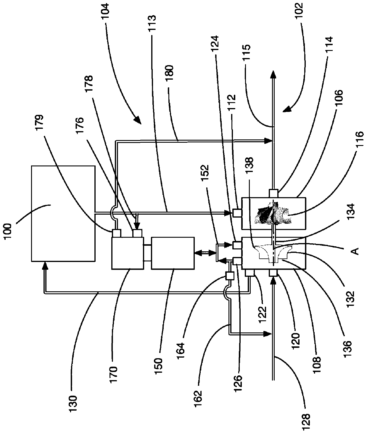
[0026] refer to figure 1 , figure 1 An internal combustion engine 100 for a vehicle is schematically shown. Engine 100 may be any suitable type of engine, such as a gasoline engine or a diesel engine.

[0027] Engine 100 receives air and fuel (eg, gasoline or diesel fuel) into its cylinders and combusts the fuel to generate power. Engine 100 has an exhaust piping system shown at 102 . Illustratively, the discharge piping system 102 is shown as a single pipe, but it will be understood that one or more portions of the discharge piping system 102 may be in the form of multiple pipes running in parallel in the discharge piping system 102 .

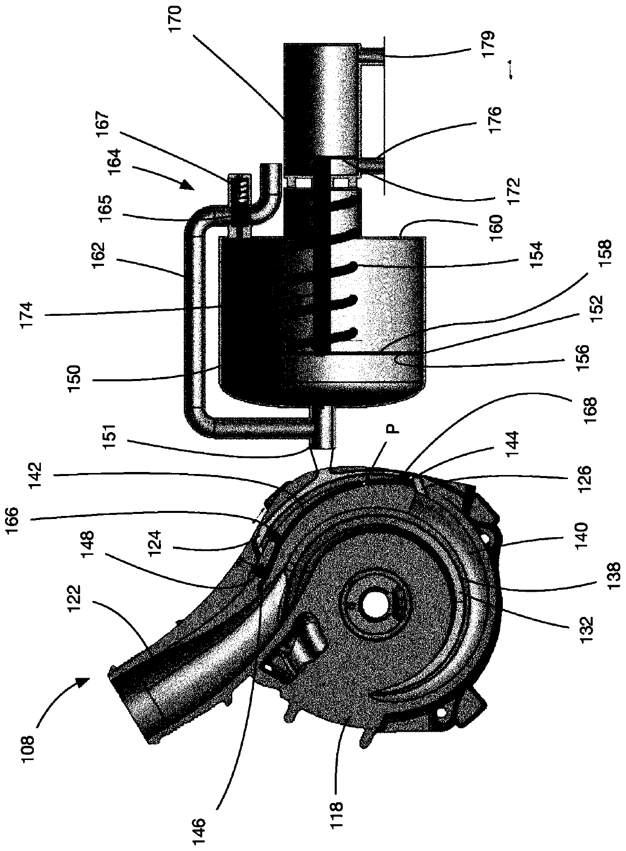
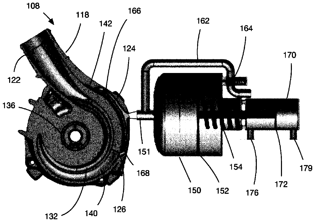
[0028] A turbocharger system 104 is provided in accordance with embodiments of the present disclosure. The turbocharger system 104 includes, among other things, a turbocharger 106 and a compressor 108 . In some embodiments, the turbocharger system 104 improves the performance of the engine 100 relatively inexpensively without changing the...


PUM


Abstract

In an aspect, a method is provided for controlling air flow to an internal combustion engine, comprising: providing a turbocharger and a compressor that is driven by the turbocharger; driving rotationof a turbine of the turbocharger using exhaust gas from the engine; driving rotation of an impeller of the compressor to generate pressurized air for the engine; sending pressurized air from a pressurized air storage chamber to the internal combustion engine if the pressurized air generated by the impeller is sufficiently low; and sending pressurized air from the compressor to the pressurized airstorage chamber for storage therein if the pressurized air generated by the impeller is sufficiently high.

Description

[0001] cross reference [0002] This application claims the benefit of US Provisional Application No. 62 / 472,992, filed March 17, 2017, and US Provisional Application No. 62 / 536,299, filed July 24, 2017. The contents of these applications are incorporated herein by reference. technical field [0003] The present disclosure relates generally to turbochargers, and more particularly to methods and systems for improving turbocharger performance. Background technique [0004] A turbocharger is a well-known device for increasing the amount of power produced by an internal combustion engine in a vehicle. However, some turbochargers have certain problems, such as lag (also known as "turbo lag"), which is when the vehicle accelerates with the engine at low RPM It takes an unacceptably long time to meaningfully boost the engine's power. [0005] To reduce the severity of turbo lag, some companies have developed relatively complex systems to adjust the geometry of the turbine on the...

Claims


Application Information

Patent Timeline
IPC IPC(8): F02B37/12F02B37/24F02D23/00F04D29/46
CPCF02B21/02F02B33/44F02B37/10F02B37/16F02B37/18F02B37/183F02B37/225F02D23/00F04D27/002F04D29/4206Y02T10/12
Inventor 贾正杰
Owner LITENS AUTOMOTIVE INC
Why Eureka
Eureka Blog
Learn More