Displays and Head Mounted Displays

A display device and display panel technology, which is applied to static indicators, instruments, semiconductor devices, etc., can solve the problems of insufficient color reproducibility and brightness, and cannot fully eliminate the afterglow of phosphors, and achieve the effect of suppressing afterglow

Active Publication Date: 2022-07-19
SHARP KK +1
View PDF8 Cites 0 Cited by
  • Summary
  • Abstract
  • Description
  • Claims
  • Application Information

AI Technical Summary

Problems solved by technology

However, when the light source is changed to an LED and the type of phosphor is changed accordingly, the afterglow of the phosphor may not be sufficiently eliminated by the above-mentioned duty driving method, and the light emitted by the phosphor may not be sufficiently eliminated. Color reproduction and brightness may also become insufficient

Method used


Image

  • Displays and Head Mounted Displays
  • Displays and Head Mounted Displays
  • Displays and Head Mounted Displays

Examples


Embodiment approach 1

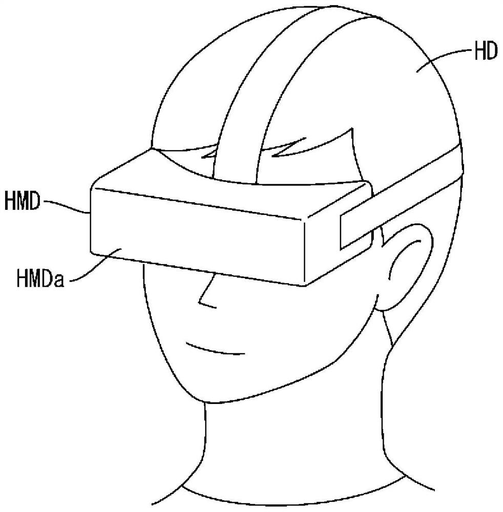
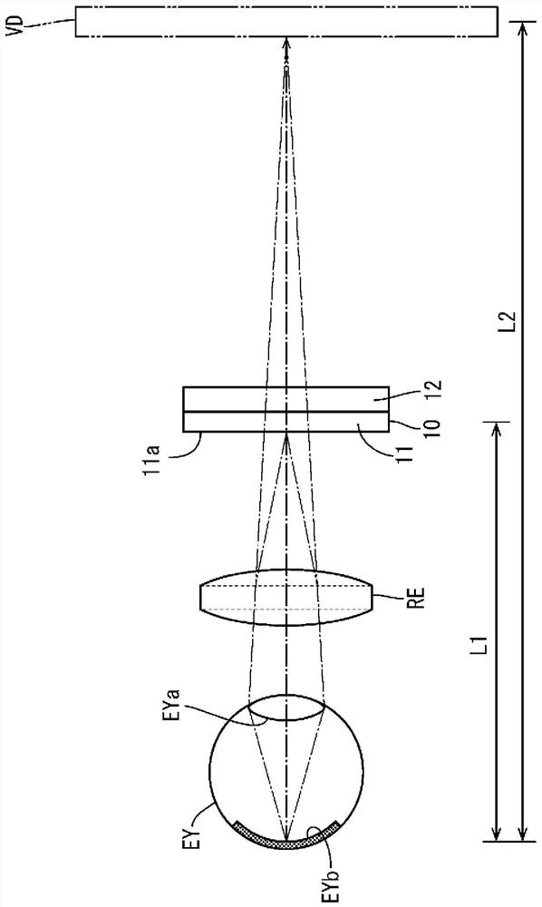
[0037] use Figure 1 to Figure 9 Embodiment 1 of the present invention will be described. In the present embodiment, a goggle-type head-mounted display (HMD: Head-Mounted Display) HMD and a liquid crystal display device (display device) 10 used therein are exemplified. The X-axis, the Y-axis, and the Z-axis are shown in a part of each of the drawings, and the directions of the respective axes are drawn in the directions shown in the drawings.

[0038] like figure 1 As shown, the goggle-type head-mounted display HMD includes a head-mounted device HMDa that can be worn on the user's head HD so as to surround both eyes. like figure 2 As shown, the head mounted device HMDa includes at least: a liquid crystal display device 10 for displaying an image; and a lens portion (eyepiece portion) RE for making the image displayed on the liquid crystal display device 10 appear on the eyeball of the user (Eye) Imaging at EY. The liquid crystal display device 10 includes at least a liqu...

Embodiment approach 2

[0068] use Figures 10 to 12 Embodiment 2 of the present invention will be described. In this Embodiment 2, the structure and control of the backlight device 112 are changed and described. For the same structure, function, and effect as those of the above-described first embodiment, overlapping descriptions are omitted.

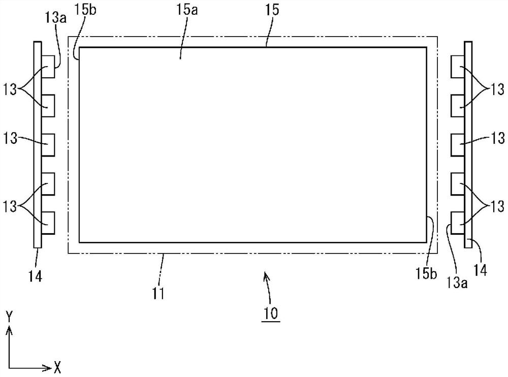
[0069] The light guide plate 115 constituting the backlight device 112 of this embodiment is as Figure 10 and Figure 11 As shown, a prism (directivity light guide portion) 26 is provided on the light-emitting plate surface 115a. The prism 26 has a mountain shape with a substantially triangular (substantially right-angled triangle) cross-sectional shape, and is a ridge extending linearly along the X-axis direction (the normal direction of the light-emitting surface 113a of the LED 113 ), and is on the surface of the light-emitting plate surface 115a. A plurality of them are arranged in a row along the Y-axis direction. The apex angle of the prism 26 is ...


PUM


Abstract

The liquid crystal display device 10 includes: a liquid crystal panel 11; a backlight device 12; The backlight control unit 21 that controls the driving of the LEDs 13 in synchronization with the display of the liquid crystal panel 11 , and the backlight control unit 21 controls the driving of the LEDs 13 so that one frame display period of the liquid crystal panel 11 includes dots The bright period and the extinguishing period; the composite fluoride red phosphor constituting the red phosphor, the content ratio of which is in the range of 50% or more and 85% or less; and the nitride-based red phosphor constituting the red phosphor, the content ratio of which is 15% % or more and 50% or less.

Description

technical field [0001] The present invention relates to a display device and a head mounted display. Background technique [0002] Conventionally, as an example of a liquid crystal display device, a liquid crystal display device disclosed in the following Patent Document 1 is known. The light source control unit of the control circuit included in the liquid crystal display device disclosed in Patent Document 1 outputs a light emission control signal to each light source power supply circuit in synchronization with a latch pulse signal output from the gate driver control unit to the gate driver. Each light source power supply circuit switches the light emission state of the cold cathode tube to any one of the first to third light emission states based on the input light emission control signal, and illuminates the LCD panel from the back of the display area. The light-emitting state of the first stage is an off state, the light-emitting state of the second stage is a maximum...

Claims


Application Information

Patent Timeline
Patent Type & Authority Patents(China)
IPC IPC(8): G02F1/13357G02F1/13G02F1/133
CPCG02F1/133615G02B6/0068G02B6/0013G02B6/0038C09K11/675C09K11/645G02B2027/0112G02B27/0172H01L33/502G09G3/002G09G3/3406G02F1/133601G02F1/133614C09K11/77348G02F1/1336
Inventor 林德美初田宪一赤川星太郎森川武
Owner SHARP KK
Why Eureka
Try Eureka