Water leakage prevention device in hysteroscopy

A leak-proof device and hysteroscope technology, applied in the directions of surgery, endoscopy, colposcopy, etc., can solve the problems of easy water leakage and affect the effect of uterine distention, and achieve the effect of avoiding air leakage

Pending Publication Date: 2019-11-22
AFFILIATED HOSPITAL JIANGNAN UNIV WUXI NO 4 PEOPLES HOSPITAL
View PDF0 Cites 0 Cited by
  • Summary
  • Abstract
  • Description
  • Claims
  • Application Information

AI Technical Summary

Problems solved by technology

[0003] The purpose of the present invention is to provide a kind of anti-leakage device in hysteroscopic surgery to solve the problem that water is easy to leak and affect the effect of uterine distension when the cervix is ​​distended in the above-mentioned background technology

Method used


Image

  • Water leakage prevention device in hysteroscopy
  • Water leakage prevention device in hysteroscopy
  • Water leakage prevention device in hysteroscopy

Examples


Embodiment 1

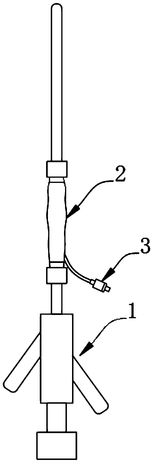
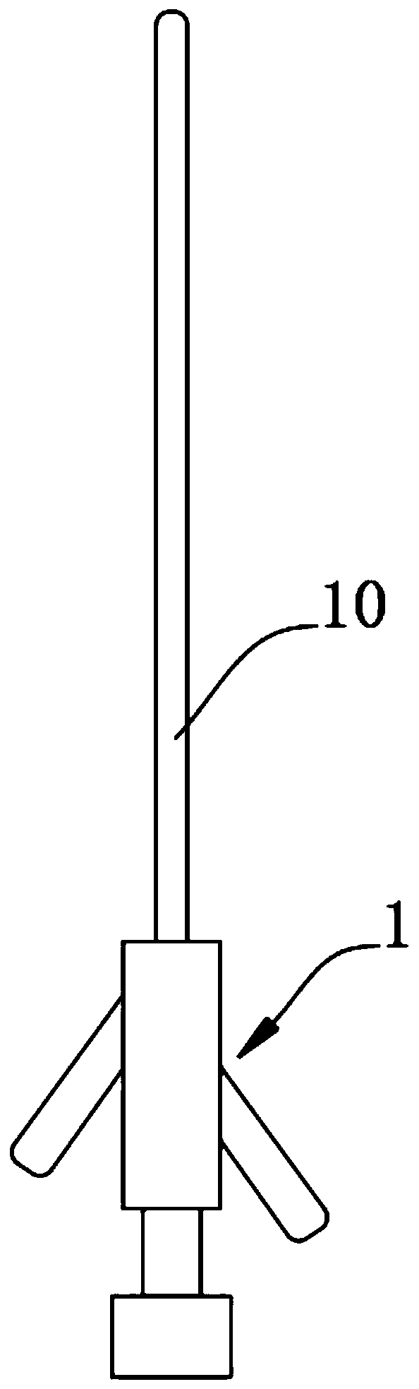
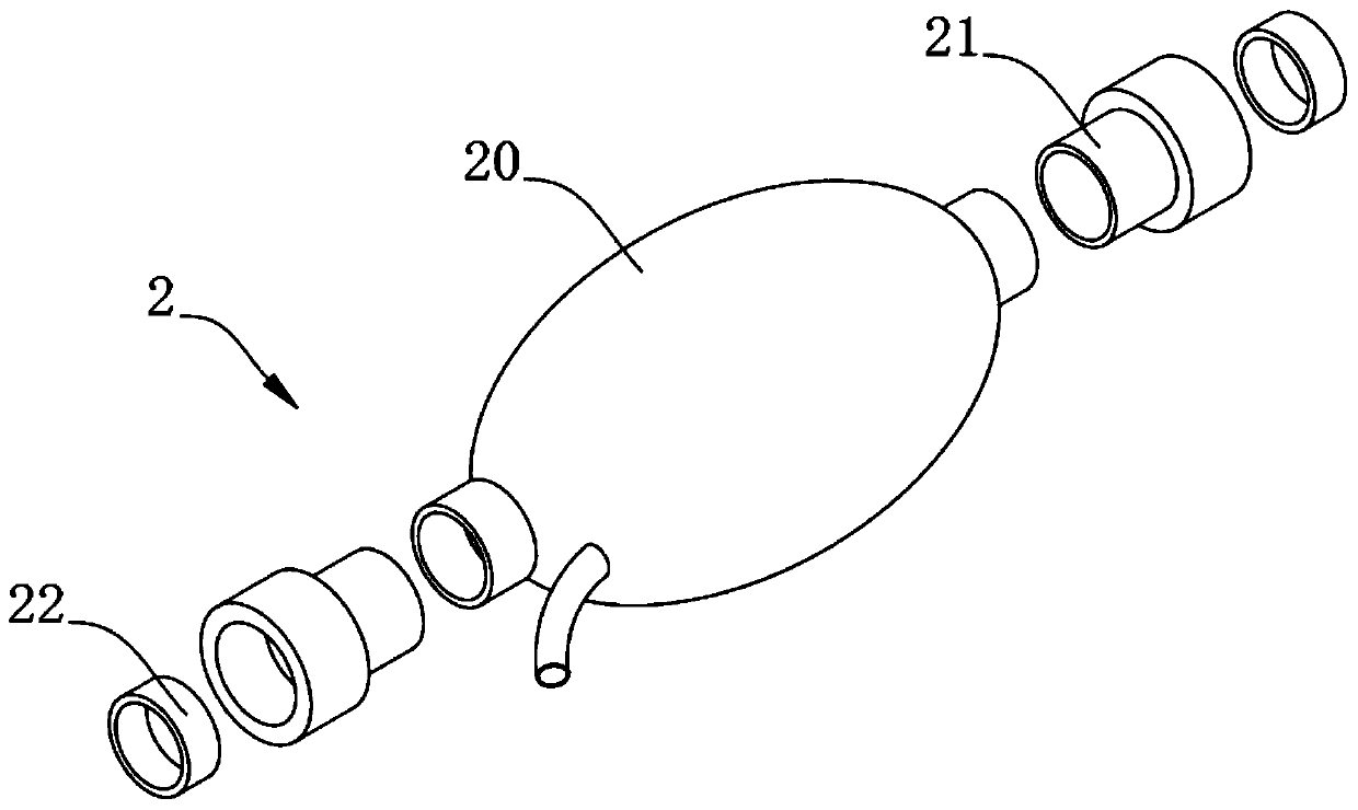
[0025] A kind of anti-leakage device in the hysteroscopic operation, in order to leak the water of cervix dilatation, influence operation to carry out, the inventor has provided anti-leakage device 2, as a preferred embodiment, as figure 1 , figure 2 , image 3 , Figure 4 with Figure 5 As shown, a hysteroscope 1 is included, and the top of the hysteroscope 1 is connected with a leak-proof device 2. The leak-proof device 2 includes an air bag 20, and the two ends of the air bag 20 are connected with a sleeve column 21, and the inner side of the outer end of the sleeve column 21 is connected with a The sealing ring 22, the two ends of the airbag 20 are provided with a sleeve head 200, the outside of one end of the airbag 20 is provided with a vent pipe 201, one end of the sleeve 21 is provided with a sleeve hole 210, and the other end of the sleeve 21 is provided with a boss 211.

[0026] In this embodiment, the airbag 20 and the sealing ring 22 are made of silica gel, whi...

Embodiment 2

[0031] As the second embodiment of the present invention, in order to facilitate gas injection at any time and avoid gas leakage, the inventor has provided a gas injection device 3, as a preferred embodiment, as Image 6 As shown, one end of the anti-leakage device 2 is connected with a gas injection device 3, the gas injection device 3 includes a gas injection column 30, a spring 31 is arranged on the inner side of the gas injection column 30, a backing plate 32 is provided at one end of the spring 31, and the backing plate 32 A limiting plate 320 is provided on one side of the air injection column 30 , and one end of the gas injection column 30 is connected with a limiting cap 33 .

[0032] In this embodiment, the gas injection device 3 is made of PP material, namely polypropylene, which is light in weight, good in toughness, rigid in strength and durable in use.

[0033] Specifically, one end of the gas injection column 30 is provided with a connecting column 300 , which is...


PUM


Abstract

The invention relates to the technical field of auxiliary devices, especially to a water leakage prevention device in hysteroscopy. The device includes a hysteroscope, the upper part of which is connected with a leakage-proof device; one end of the leakage-proof device is connected with a gas injection device; the leakage-proof device comprises a gas bag, two ends of which are connected with sleeve columns; sealing rings are connected to the inner sides of the outer ends of the sleeve columns; the gas injection device comprises a gas injection column, the inner side of which is provided with aspring; one end of the spring is provided with a base plate; a limiting plate is disposed on one side of the base plate; and one end of the gas injection column is connected with a limiting cap. By inflating at a breather pipe, the gas bag is expanded to compact a gap between an endoscope sheath and the cervix uteri, water leakage is avoided, and an operation can be performed smoothly. When an injector is used for gas injection, the limiting plate is arranged to block a cap hole of the limiting cap under the action of the spring, and then air leakage is avoided. During inflating, the limitingplate only needs to be ejected open by the injector, and then the air bag can be inflated to expand.

Description

technical field [0001] The invention relates to the technical field of auxiliary devices, in particular to a water leakage prevention device in hysteroscopy. Background technique [0002] At present, there are more and more hysteroscopic operations, and more and more patients encounter cervical relaxation. The uterus needs water to expand the uterus during hysteroscopic surgery. If there is a gap between the cervix and the hysteroscopic sheath, water will leak out and the pressure will increase. If it is too small, satisfactory uterine distension cannot be achieved during the operation, which makes the operation time-consuming and laborious, and the progress is not smooth. In view of this, we propose a kind of anti-leakage device in hysteroscopy. Contents of the invention [0003] The purpose of the present invention is to provide an anti-leakage device for hysteroscopic surgery to solve the problem in the above-mentioned background art that water is easy to leak when the...

Claims


Application Information

Patent Timeline
Patent Type & Authority Applications(China)
IPC IPC(8): A61B1/303A61B1/00A61B17/42
CPCA61B1/00082A61B1/303A61B17/4241A61B2017/4225
Inventor 董春林
Owner AFFILIATED HOSPITAL JIANGNAN UNIV WUXI NO 4 PEOPLES HOSPITAL
Why Eureka
Try Eureka