[0019] In order to make it easy to understand the technical means, creative features, goals and effects achieved by the present invention, the present invention will be further explained below in conjunction with specific embodiments.
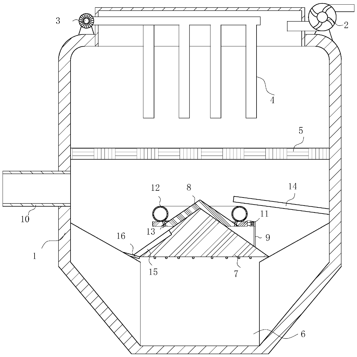
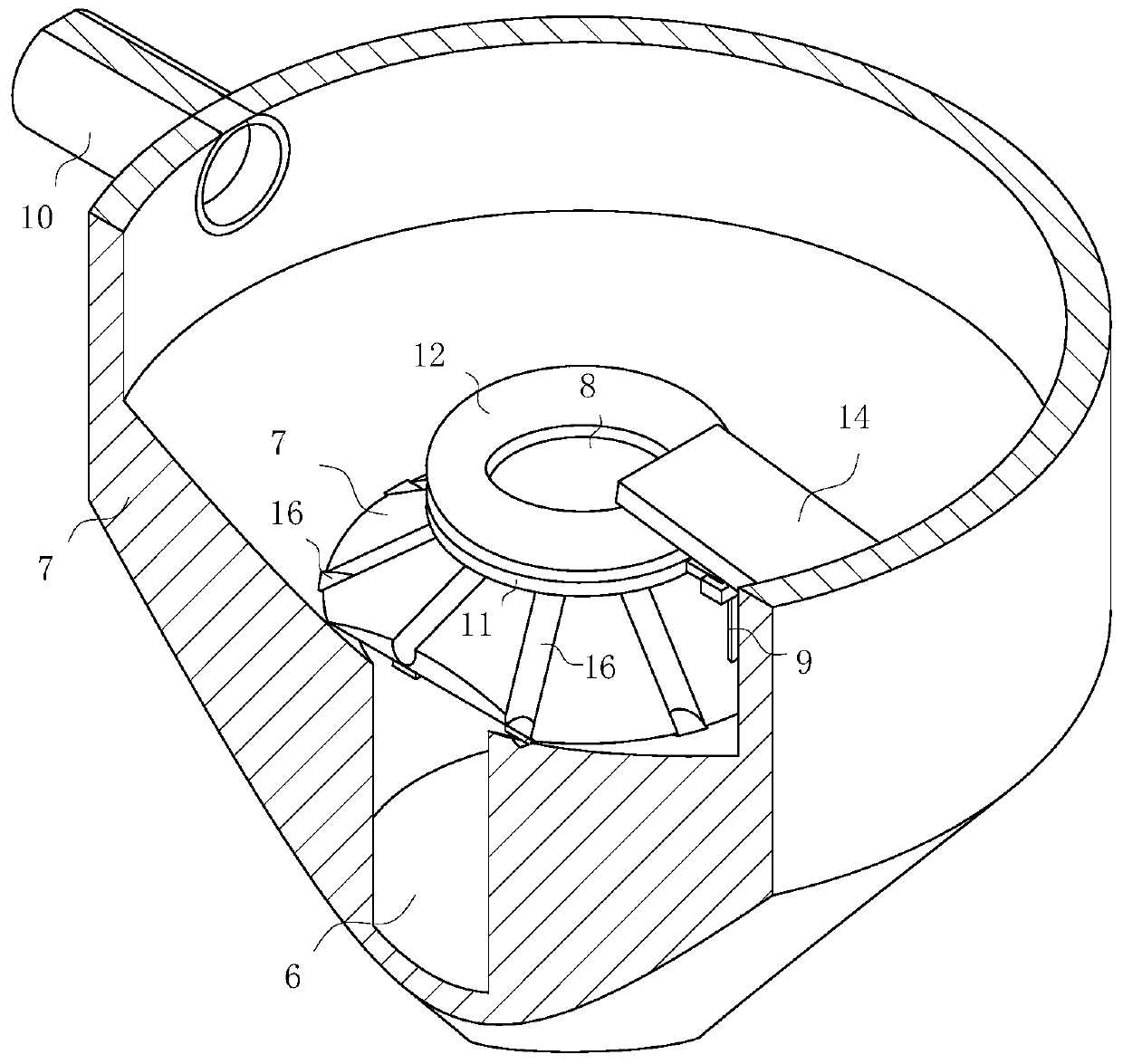
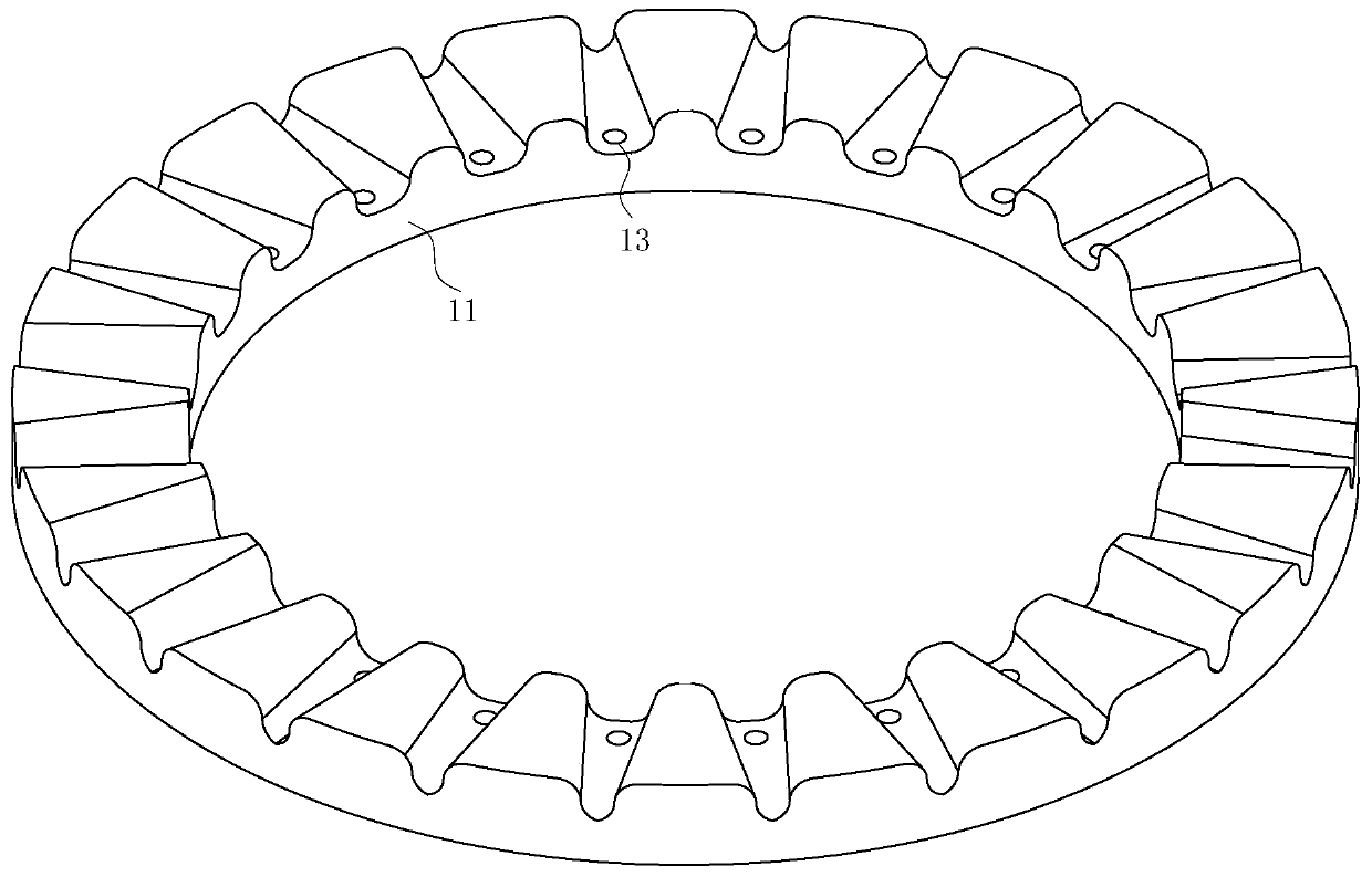
[0020] Such as Figure 1-3 As shown, an industrial dust collector according to the present invention includes a body 1, a fan 2 is provided on the top of the body 1, a pulse valve 3 is provided on the top of the fan 2, and a blow pipe 4 is connected to the pulse valve 3 The inner middle of the body 1 is provided with a filter bag 5, the bottom of the body 1 is provided with a collection chamber 6, the top of the collection chamber 6 is provided with a main cone 7, the bottom edge of the main cone 7 does not contact the inner wall of the body 1, the main cone The top of the disc 7 is sleeved with an auxiliary cone disc 8, a connecting rod 9 is hinged on one side of the auxiliary cone disc 8, and the bottom end of the connecting rod 9 is fixedly connected with the main cone disc 7; the body 1 is connected with an air inlet pipe 10; , When the exhaust fan 2 is turned on for a period of time, the air in the body 1 will first be pumped out, and the air in the body 1 will rise. Due to the blocking of the main cone 7, the wind can only flow from the main cone 7 and the inner wall of the body 1 The dust in the collection chamber 6 that is drawn in the gap between the two rises, and the area of the drawn dust is small, which reduces the amount of gas drawn into the collection chamber 6 at the bottom of the main cone 7 to reach the filter bag 5, ensuring the filter bag The dust removal effect of 5, and at the same time, due to the action of the pumping air, there will be a bottom-up thrust to drive the bottom of the auxiliary cone 8, and then the main cone 7 is driven by the auxiliary cone 8. When the main cone 7 is driven to rise Because the auxiliary cone 8 is hinged with the connecting rod 9, it will change from the horizontal state to the inclined state. At this time, the inclined auxiliary cone 8 has a reduced blocking effect on the upwardly moving wind, and the upwardly moving wind has a negative effect on the auxiliary cone 8 Since the main cone 7 is far from the fan 2, the suction force it receives is small. Therefore, when the rising force of the auxiliary cone 8 is reduced, the auxiliary cone 8 can no longer pull the main cone 7, The gravity of the main cone disk 7 drives the auxiliary cone disk 8 to move downwards. When the main cone disk 7 moves down, the dust in the collection chamber 6 that is drawn by the wind through the gap between the main cone disk 7 and the inner wall of the body 1 is affected. The effect of pressure further reduces the amount of dust rising to reach the filter bag 5. Finally, when the fan 2 works for a short period of time, the body 1 is in a stable state, and the fan 2 draws air to be dusted from the outside through the air intake pipe 10. After the air to be dusted enters the body 1, it reaches the surface of the filter bag 5, and the dust is filtered by the filter bag 5. After the fan 2 works for a period of time, the pulse valve 3 can generate a stronger air flow to clean the dust on the filter bag 5 It falls to the bottom of the inside of the body 1, and finally the dust-filtered air is drawn out of the body 1 by the fan 2, and the fan 2 stops working. Repeat the above operation after a period of time.
[0021] The outer side of the auxiliary cone plate 8 is fixedly connected with an annular plate 11, the top of the annular plate 11 is provided with an annular capsule 12, and the bottom of the annular capsule 12 is provided with an air jet hole 13 which extends through the annular plate 11 to the bottom of the auxiliary cone plate 8; 1 An inclined plate 14 is fixedly connected to the inner wall, and the bottom surface of the inclined plate 14 is in contact with the top of the annular capsule 12; when the auxiliary cone 8 is moved upward by the twitching wind, the annular capsule 12 on the top of the annular plate 11 is driven to squeeze on the inclined plate 14. The gas is forced out through the jet hole 13 and finally blown on the upper surface of the main cone 7, the gas is blown downward by the guiding action of the inclined upper surface, and the rising dust can be directed downwards before the main cone 7 descends. The blowing effect further reduces the amount of dust rising.
[0022] The surface of the main cone disk 7 is evenly distributed with a plurality of diversion grooves 15, and the top of the diversion groove 15 is located on the extension line of the air injection hole 13; When the gas squeezed out in 12 is sprayed into the diversion groove 15 through the jet hole 13, the wind can be gathered together by the diversion groove 15 to prevent it from being scattered on the upper surface of the main cone 7 and finally pass through the diversion The wind gathered in the groove 15 reaches the bottom end of the guide groove 15 along the guide groove 15. The blown wind has greater strength and can be drawn from the gap between the main cone 7 and the inner wall of the body 1 in the collection chamber 6 The dust has a better effect of blowing downwards, and at the same time, the dust falling in the guide groove 15 can be blown downwards at the beginning of work, thereby reducing the residual dust.
[0023] The cross section of the diversion groove 15 is peach-shaped; when the diversion groove 15 is viewed obliquely upward, the diversion groove 15 is peach-shaped, and the width of the middle of the diversion groove 15 is large, and the gas ejected from the jet hole 13 enters When it enters the guide groove 15 and moves below the body 1 along the guide groove 15, a part of the wind passing through the guide groove 15 will be blocked by the main cone 7 and blow out from the guide groove 15 through the guide groove 15 When the upper opening is sprayed, there will be a stronger force, which will disturb the rising small amount of dust, reduce the time for dust to rise, and reduce the height of the rise. Finally, when the inside of the body 1 is completely stable, the dust will move towards Prevent dust from reaching the filter bag 5.
[0024] The upper surface of the annular plate 11 is set as a wavy surface, and the part of the jet hole 13 located on the annular plate 11 passes through the trough; after the fan 2 has been working for a period of time, the dust falling from the surface of the annular bag 12 to the surface of the annular plate 11 The upper surface of the ring plate 11 is a wavy surface and gathers at the trough of the wave surface. Under the action of the gas ejected through the jet holes 13, the dust can be removed from the surface of the ring plate 11 and the residue of dust can be reduced.
[0025] A blocking rod 16 is fixedly connected to the inner wall of the body 1, and the blocking rod 16 is in contact with the bottom end of the diversion groove 15. The blocking rod 16 is used to block the bottom end of the diversion groove 15; The gap between the main cone 7 and the inner wall of the body 1 acts as a barrier to reduce the gap between the larger main cone 7 and the inner wall of the body 1 generated after the guide groove 15 is opened.
[0026] During operation, when the exhaust fan 2 is turned on for a period of time, the air in the body 1 will first be pumped out, and the air in the body 1 will rise. Due to the blocking of the main cone 7, the wind can only flow from the main cone 7 and the body 1. The dust in the collection chamber 6 drawn in the gap between the inner walls rises, and the area of the drawn dust is small, which reduces the amount of gas in the collection chamber 6 at the bottom of the main cone 7 to reach the filter bag 5 by pumping it. The dust removal effect of the filter bag 5, at the same time, due to the action of the pumping air, there will be a bottom-up thrust to drive the bottom of the auxiliary cone 8, and then the main cone 7 is driven by the auxiliary cone 8. When the main cone 7 is driven When ascending, the auxiliary cone 8 is hinged with the connecting rod 9 to transform from the horizontal state to the inclined state. At this time, the inclined auxiliary cone 8 has a reduced blocking effect on the upwardly moving wind, and the upwardly moving wind affects the auxiliary cone 8 The reaction force of the main cone 7 is reduced. Because the main cone 7 is far away from the fan 2, the suction force it receives is small. Therefore, when the rising force of the auxiliary cone 8 is reduced, the auxiliary cone 8 can no longer pull the main cone 7 Function, the gravity of the main cone disc 7 drives the auxiliary cone disc 8 to move downwards. When the main cone disc 7 moves down, it can oppose the dust in the collection chamber 6 that is drawn by the wind through the gap between the main cone disc 7 and the inner wall of the body 1 It has the effect of downward pressure, which further reduces the amount of dust rising and reaching the filter bag 5. Finally, when the fan 2 works for a short period of time, the body 1 is in a stable state, and the fan 2 extracts the dust to be removed from the outside through the air inlet pipe 10. Air, after the air to be dusted enters the body 1, it reaches the surface of the filter bag 5, and the dust is filtered by the filter bag 5. After the fan 2 works for a period of time, the pulse valve 3 can generate a stronger air flow, and the filter bag 5 The dust is cleaned and dropped to the bottom of the inside of the body 1, and finally the dust-filtered air is drawn out of the body 1 by the fan 2, and the fan 2 stops working. Repeat the above operation after a period of time.
[0027] The above shows and describes the basic principles, main features and advantages of the present invention. Those skilled in the industry should understand that the present invention is not limited by the foregoing embodiments. The foregoing embodiments and descriptions only illustrate the principles of the present invention. Without departing from the spirit and scope of the present invention, the present invention may have Various changes and improvements, these changes and improvements fall within the scope of the claimed invention. The scope of protection claimed by the present invention is defined by the appended claims and their equivalents.