Punch machining center

A technology of machining centers and punches, applied in metal processing equipment, manufacturing tools, presses, etc., can solve problems such as large position error, inaccurate position, and plate body offset.

Pending Publication Date: 2019-11-22
佛山市中机一超机器人科技有限公司
View PDF0 Cites 5 Cited by
  • Summary
  • Abstract
  • Description
  • Claims
  • Application Information

AI Technical Summary

Problems solved by technology

[0002] In the existing punch processing center, the grip force on the pressing plate is not enough, and the phenomenon of plate body deviation often occurs. On the one hand, the position of the plate body on the punching bed is inaccurate and deviated, resulting in a large position error during punching; at the same time, In the existing punch processing center, after the grabbing manipulator extends into the punch machine, the phenomenon of scratching the plate body may occur due to the insufficient clamping force of the manipulator

Method used


Image

  • Punch machining center
  • Punch machining center
  • Punch machining center

Examples


Embodiment Construction

[0056] The technical solutions of the present invention will be further described below through specific embodiments in conjunction with the accompanying drawings.

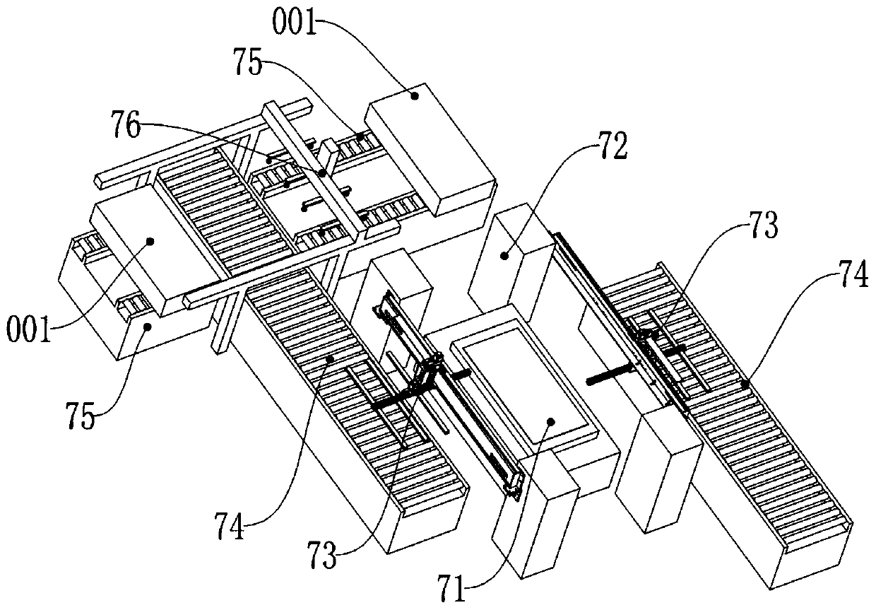
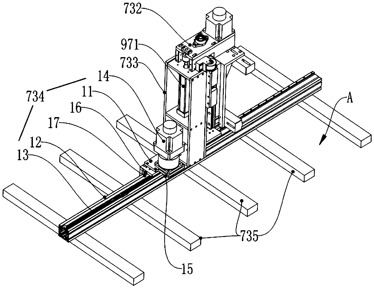
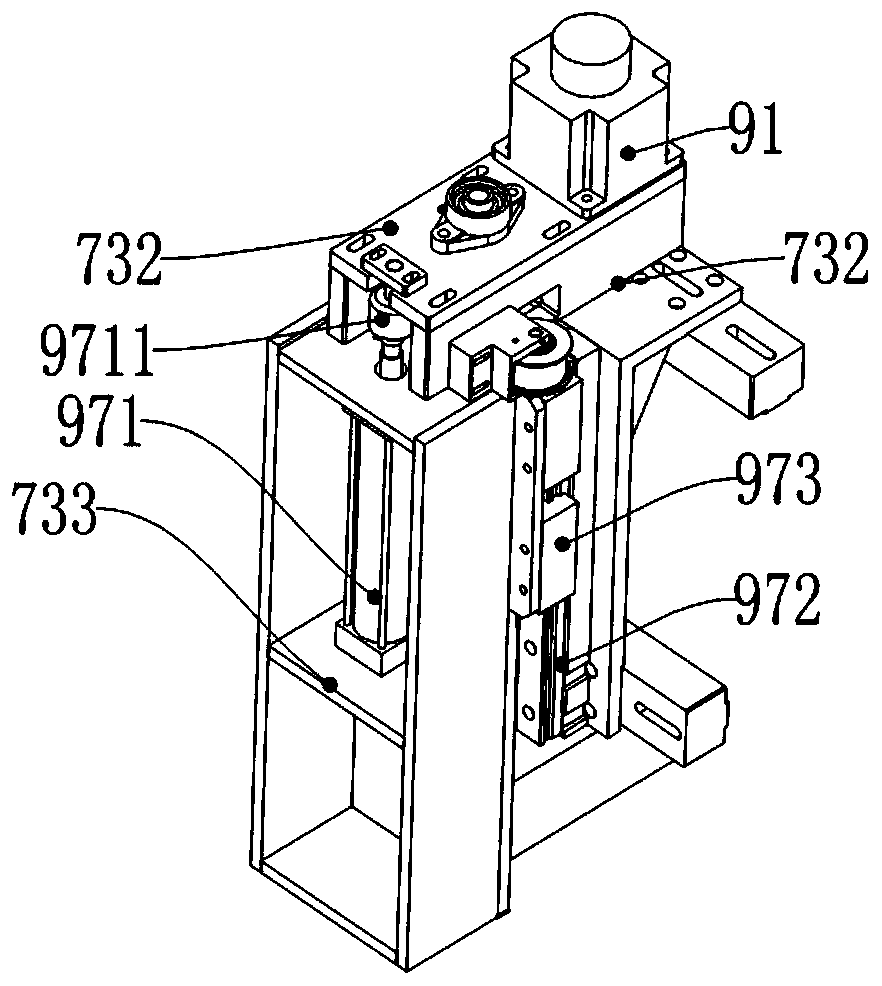
[0057] A punch processing center, comprising: a punch 71, a punch frame 72, a feeding manipulator 73, a feeding conveying line 74, a moving conveying line 75, and a feeding manipulator device 76;

[0058] The stamping frame 72 is located on both sides of the punch 71; the feeding conveying line 74 is provided with at least two, and the two feeding conveying lines 74 are respectively located on the left and right sides of the punch 71; The material transfer manipulator 73 is installed on the stamping frame 72; the active area of ​​the material transfer manipulator 73 includes the top of the feeding conveyor line 74; Both sides; the feeding manipulator device 76 is located above the feeding conveying line 74, and its grasping end can move up and down, and passes above the feeding conveying line 74 and the moving conve...


PUM


Abstract

A punch machining center is characterized by comprising a punch press, a punching rack, a material conveying manipulator, a feeding conveying line, a moving conveying line and a feeding manipulator device, wherein a material conveying lifting motor is arranged on a lifting fixing plate, and the output end of the material conveying lifting motor is coaxially equipped with a material conveying lifting driving wheel; one end of the material conveying lifting screw rod is rotatably arranged on the lifting fixing plate, and a material conveying lifting driven wheel is matched with the lifting fixing plate; the material conveying lifting conveyor belt is connected with the material conveying lifting driving wheel and the material conveying lifting driven wheel; a lifting slide seat is provided with a material conveying lifting nut seat; and a material conveying lifting screw rod is matched with the material conveying lifting nut seat. The punch machining center is capable of automatically conveying articles and sending the articles to the punch through the material conveying manipulator, and after the punch completes machining, the material conveying manipulator takes the articles out ofthe punch, so that the steps of automatically feeding, punching and discharging the articles are realized.

Description

technical field [0001] The invention relates to the technical field of punch processing centers, in particular to a punch processing center. Background technique [0002] In the existing punch processing center, the grip force on the pressing plate is not enough, and the phenomenon of plate body deviation often occurs. On the one hand, the position of the plate body on the punching bed is inaccurate and deviated, resulting in a large position error during punching; at the same time, In the existing punch processing center, after the grabbing manipulator extends into the punch press, the phenomenon of scratching the plate body may occur due to insufficient clamping force of the manipulator. Contents of the invention [0003] The object of the present invention is to provide a punch processing center with a material transfer manipulator, a feeding conveying line and a moving conveying line. [0004] For reaching this purpose, the present invention adopts following technical...

Claims


Application Information

Patent Timeline
Patent Type & Authority Applications(China)
IPC IPC(8): B21D43/02B21D43/18B30B15/32B30B15/30
CPCB21D43/02B21D43/18B30B15/30B30B15/32
Inventor 宋建新
Owner 佛山市中机一超机器人科技有限公司
Why Eureka
Try Eureka