Automatic tin immersion device and flat cable processing production line

A production line and immersion tin technology, which is applied in the direction of tin feeding devices, auxiliary devices, metal processing equipment, etc., can solve problems such as difficult to scrape off, low quality of wiring, incomplete tin scraping, etc., and achieve the effect of saving labor costs

Pending Publication Date: 2019-11-22
CHONGQING HONGLIN TECH
View PDF0 Cites 7 Cited by
  • Summary
  • Abstract
  • Description
  • Claims
  • Application Information

AI Technical Summary

Problems solved by technology

[0004] In the existing automatic tin dipping device, when the core wire is lifted from the tin bath, only one scraper is used to directly scrape the tin on the wire. The core wires of the cable will also stick to each other, and the quality of the obtained cable is not high; the inner cutting, inner removal, flux addition, tin liquid pre-dipping and core wire of the core wires at both ends of the cable can be completed at one time cutting

Method used


Image

  • Automatic tin immersion device and flat cable processing production line
  • Automatic tin immersion device and flat cable processing production line
  • Automatic tin immersion device and flat cable processing production line

Examples


Embodiment 1

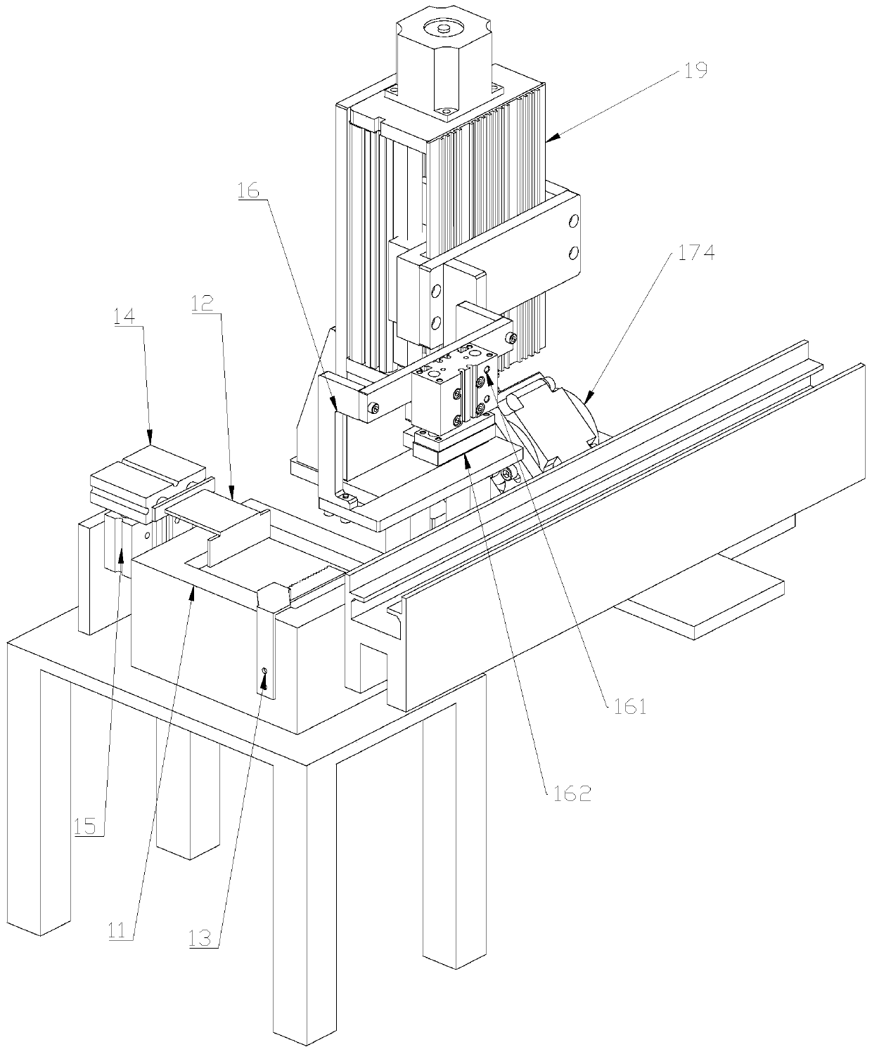
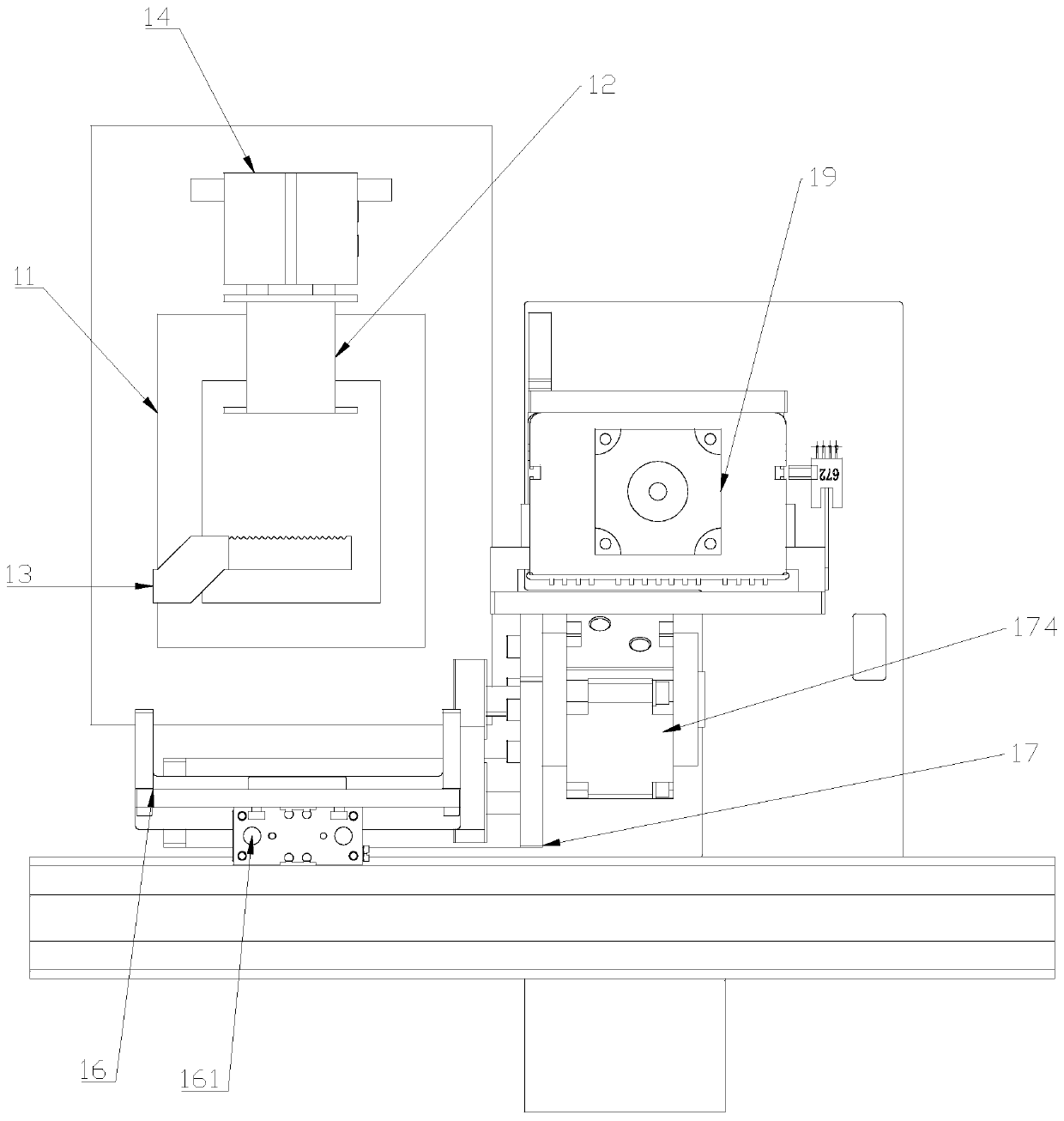
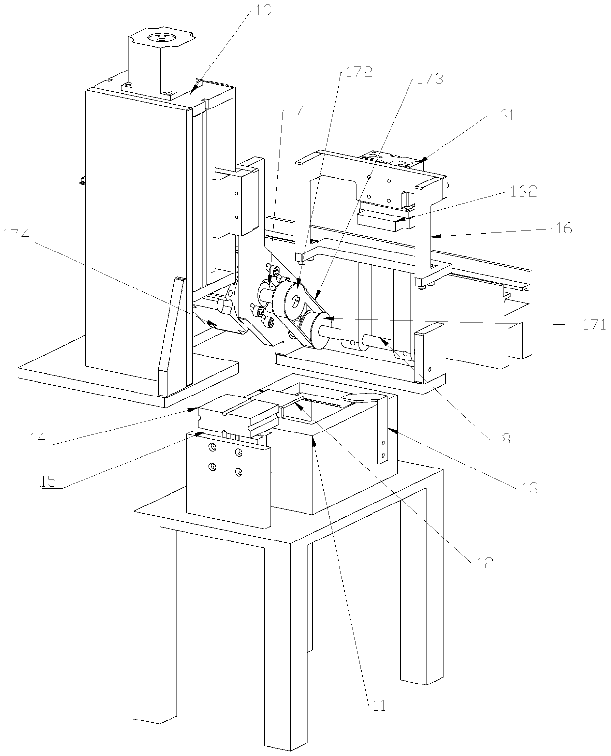
[0034] An automatic immersion tin device, such as Figure 1 to Figure 3, the overturning mechanism is connected to the PLC motor 19 as a whole, and the PLC motor 19 is fixedly set. When the automatic tin dipping device 1 works, the PLC motor drives the entire overturning mechanism to move upward for a certain distance until the horizontal end surface below the cross-shaped structure of the overturning part 16 and the clip The wire fixture 24 contacts, and then the third cylinder 161 on the turning part 16 pushes the splint 162 to move downward to clamp the wire clamping fixture 24; the PLC motor 19 drives the entire turning mechanism to move upward for a certain distance, so that the clamping fixture 24 times The end surface is away from the top of the positioning pin on the fixture base 23; the control part 17 drives the turning part 16 to turn 90 degrees toward the tin bath 11 through the synchronous toothed belt structure, so that the cable on the clamping fixture 24 is imme...

Embodiment 2

[0042] A line processing production line, such as Figure 4 and Figure 5 , including the above-mentioned automatic tin dipping device 1, the specific use process is the same, the automatic tin dipping device 1 is located on one side of the conveying track 2, and the other side of the conveying track 2 is fixedly installed with a sensor 21 and a limit baffle 22 and is connected with the automatic dipping tin Tin device 1 position is relative, and limit baffle 22 in the sensor 21 and limit baffle 22 is closer to the end of conveying track 2, and the bottom of limit baffle 22 is fixedly connected with the fourth cylinder that vertically arranges. In the free state, the limit baffle plate 22 is higher than the plane of the conveying track 2. When in use, the clamping fixture 24 is placed on the fixture base 23, and the fixture base 23 moves along with the conveying track 2. When the fixture base 23 moves When reaching the limit baffle 22, the fixture base 23 is blocked by the li...


PUM


Abstract

The invention discloses an automatic tin immersion device and a flat cable processing production line. The tin immersion device comprises a tin groove and a turnover mechanism, the middle of the tin groove is provided with a groove with a fixed position, the device further comprises a first scraper plate and a second scraper plate, the first scraper plate is shaped like an Arabic number 'seven' and arranged above the tin groove, the front end of the first scraper plate shaped like the Arabic number 'seven' is a working end and stretches into the tin groove, the tail end of the first scraper plate shaped like the Arabic number 'seven' is fixedly connected with a first air cylinder arranged horizontally, a vertically-arranged second air cylinder is fixedly connected to the bottom of the first air cylinder, an evenly-arranged toothed structure is distributed at one end of the second scraper plate and horizontally stretches into the tin groove, and the other end of the second scraper plateis provided with a fixing structure for fixing the position of the second scraping plate. The automatic tin immersion device and the flat cable processing production line have the beneficial effectsthat core wires can be prevented from being stained with tin oxide by means of the automatic tin immersion device, and the core wires are separated; and inner lining cutting, inner lining removal, soldering flux adding, tin solution predipping and core wire cutting for the core wires at the two ends of a flat cable can be completed at a time by means of the flat cable processing production line.

Description

technical field [0001] The invention relates to a tin dipping device, in particular to an automatic tin dipping device and a line processing production line. Background technique [0002] Widely used in the electronics industry is a flat cable, also known as a connecting cable, which is formed by a plurality of coaxial cables with shielding layers arranged side by side, and connectors are provided at both ends of the line row, and the connectors are used to communicate with electronic equipment. Plug in the socket. The shielding wire of the connection line consists of an inner-to-outer core wire, an inner jacket, a shielding layer and an outer jacket, and the shielding layer adopts a metal braided mesh structure. The connecting wire is connected to the connection point of the connector through the core wire. When welding connection is used, the connection point on the connector is called a soldering point. In the production process of the connecting wire, it needs to go th...

Claims


Application Information

Patent Timeline
Patent Type & Authority Applications(China)
IPC IPC(8): B23K3/06B23K3/08B23K1/08H01R43/28
CPCB23K1/08B23K3/0646B23K3/08H01R43/28
Inventor 郭光华李小奇
Owner CHONGQING HONGLIN TECH
Why Eureka
Try Eureka