Cutting fluid recycling mechanism for machine tool

A cutting fluid and machine tool technology, applied in the field of machine tool cutting fluid recycling mechanism, can solve the problems of debris accumulation, affecting electromagnet recovery, uneven dispersion performance, etc., to improve uniformity, reduce metal debris content, and reduce clogging The effect of probability

Active Publication Date: 2019-11-22
苏州市业成精密机械有限公司
View PDF9 Cites 0 Cited by
  • Summary
  • Abstract
  • Description
  • Claims
  • Application Information

AI Technical Summary

Problems solved by technology

This device can efficiently filter out the metal debris in the cutting fluid and improve the recycling rate of the cutting fluid”, but there are still defects. The dispersion performance of the waste liquid containing chips and debris entering the filter screen is uneven, and the waste liquid falls into the filter screen. Concentrated location of the net can lead to accumulation of debris, affecting the recovery of the electromagnet

Method used


Image

  • Cutting fluid recycling mechanism for machine tool
  • Cutting fluid recycling mechanism for machine tool
  • Cutting fluid recycling mechanism for machine tool

Examples


Embodiment Construction

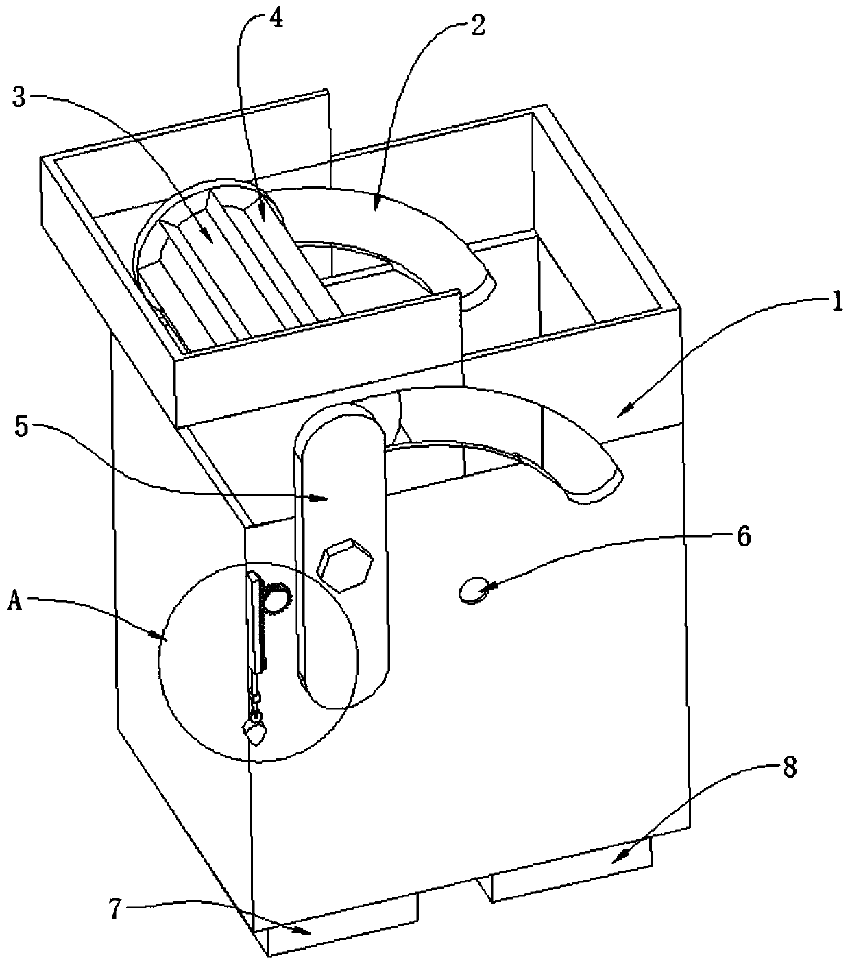
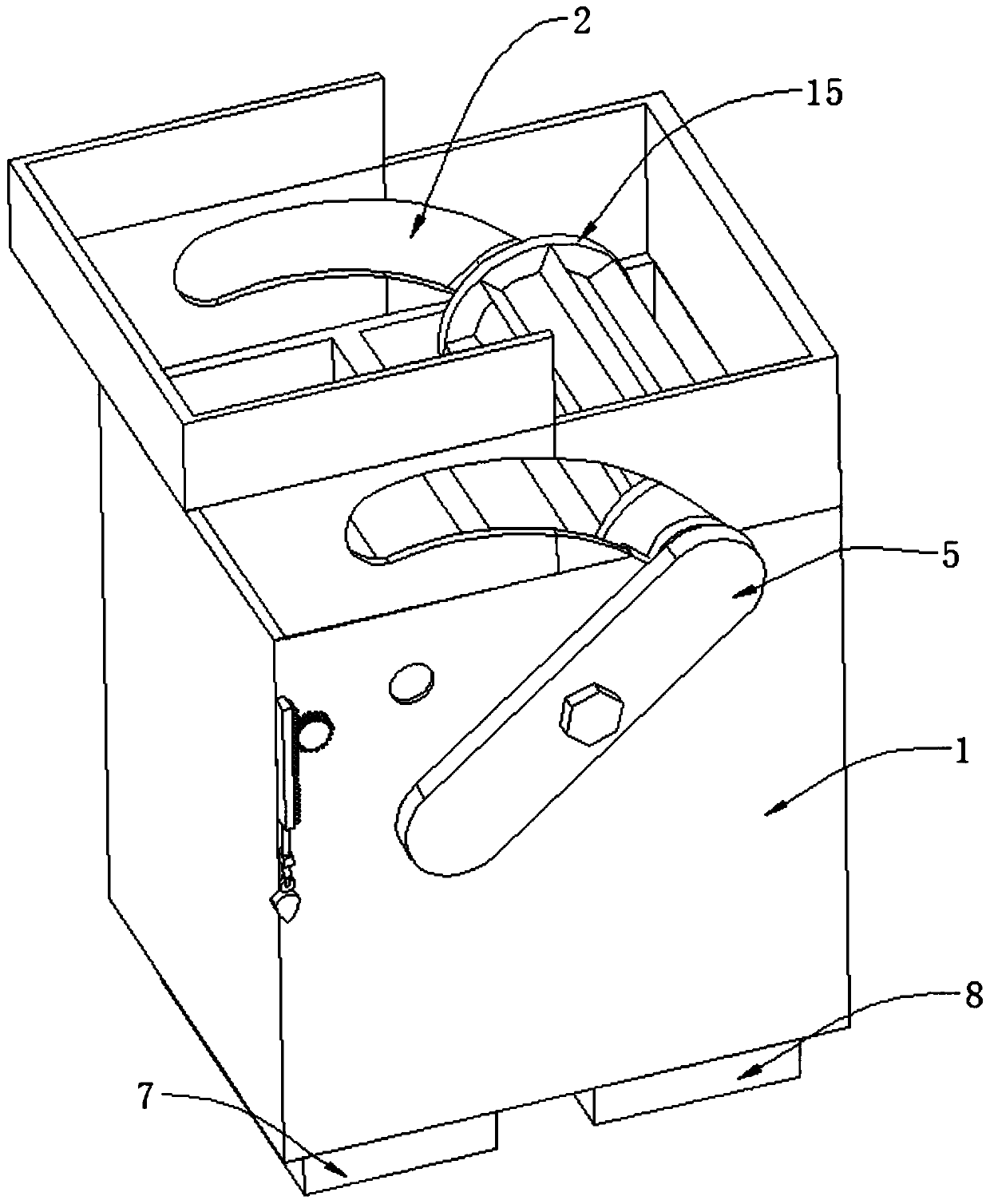
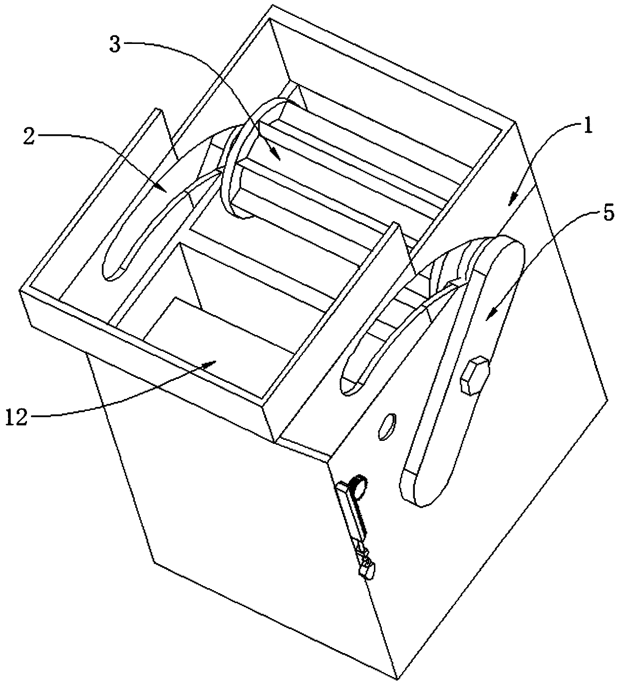
[0040] Such as Figure 1 to Figure 6 The cutting fluid recycling mechanism for machine tools shown includes a box body 1 with an open top, and also includes

[0041] The partition 14 is connected to the inner side wall of the box body 1, and separates the box body 1 into a waste liquid chamber and a waste debris chamber, and the partition 14 is provided with slots;

[0042] The adjustment groove 2 is set on the outer wall of the box body 1;

[0043] The adjusting plate 5 is rotatably connected to the outer wall of the box body 1;

[0044] The installation hole 6 is opened on the outer wall of the box body 1;

[0045] The drive roller 3 is connected between the adjustment plates 5 by being placed in the adjustment groove 2 and rotated;

[0046] The electromagnet adsorption plate 4 is evenly arranged on the outer side wall of the driving roller 3;

[0047] The blanking plate 12 is rotatably connected to the inner side wall of the box body 1 through a rotating shaft, and plac...


PUM


Abstract

The invention discloses a cutting fluid recycling mechanism for a machine tool. The cutting fluid recycling mechanism comprises a box body, a partition plate, adjusting grooves, adjusting plates, a mounting hole, a driving roller, electromagnet adsorption plates, a material falling plate and a first reciprocating adjusting assembly; the box body is provided with an opening in the top; the partition plate is connected to the inner side wall of the box body and divides the box body into a waste liquid cavity and a waste chip cavity, and an open groove is formed in the partition plate; the adjusting grooves are formed in the outer side wall of the box body; the adjusting plates are rotationally connected to the outer side wall of the box body; the mounting hole is formed in the outer side wall of the box body; the driving roller is connected between the adjusting plates in a rotating mode through rotating parts arranged in the adjusting grooves; the electromagnet adsorption plates are uniformly arranged on the outer side wall of the driving roller; the material falling plate is rotationally connected to the inner side wall of the box body through a rotating shaft and is arranged in the waste liquid cavity; and the driving end of the reciprocating adjusting assembly is connected to the rotating shaft. According to the cutting fluid recycling mechanism for the machine tool, the pretreatment function of cutting waste liquid is realized, the chip content of the cutting waste liquid when the cutting waste liquid falls into a filter plate is reduced, meanwhile, metal chippings on the filter plate are adsorbed during the filtering process of the filter plate, and the working continuity of the filter plate is improved.

Description

technical field [0001] The invention relates to a cutting fluid recycling mechanism for machine tools, which belongs to the technical field of machine tools. Background technique [0002] Cutting fluid is an industrial liquid used in metal cutting and grinding to cool and lubricate cutting tools and workpieces. Cooling performance, lubricating performance, anti-rust performance, degreasing and cleaning function, anti-corrosion function, and easy-to-dilute features, overcome the shortcomings of traditional soap-based emulsions that are easy to smell in summer, difficult to dilute in winter, and poor anti-rust effect, and have no effect on lathe paint It is suitable for the cutting and grinding of ferrous metals. It is the most advanced grinding product at present. The indicators of cutting fluid are better than saponified oil. It has good cooling, cleaning, anti-rust and other characteristics, and it is non-toxic. , odorless, non-corrosive to the human body, non-corrosive to...

Claims


Application Information

Patent Timeline
Patent Type & Authority Applications(China)
IPC IPC(8): B23Q11/10
CPCB23Q11/1069Y02P70/10
Inventor 范荣华
Owner 苏州市业成精密机械有限公司
Why Eureka
Try Eureka