
Clamp

A technology of fixtures and fixtures, which is applied in the direction of grinding workpiece supports, etc., can solve the problems of affecting working conditions, limited use, splashing, etc., and achieve the effects of reducing external dimensions, safe and stable gas supply, and suppressing splashing

Pending Publication Date: 2019-11-22
LANGFANG NORTH TIANYU ELECTROMECHANICAL TECH
View PDF1 Cites 3 Cited by
  • Summary
  • Abstract
  • Description
  • Claims
  • Application Information

AI Technical Summary

Problems solved by technology

However, clamps with locking mechanisms currently on the market still cannot meet the above requirements, and their use is often limited
[0003] Taking the fixture disclosed in the utility model patent with the patent application number of 201120093673.8 as an example, the fixture uses a locking cylinder to drive a parallelogram mechanism to lock the workpiece, although it solves the problem of loosening and shifting of machined parts caused by loosening of the fixture during machining However, there are still obvious disadvantages. The disadvantages mainly lie in: due to the large amount of abrasive and abrasive fluid in high-speed machining conditions, when the workpiece rotates at high speed, the excessively large fixture will cause a large amount of abrasive abrasive fluid to splash and affect the work. condition
However, the three-jaw fixture used on the machine tool, due to the high precision, is easy to get stuck in the chuck groove, which directly affects the clamping and cannot work.

Method used


Image

  • Clamp
  • Clamp
  • Clamp

Examples


Embodiment 1

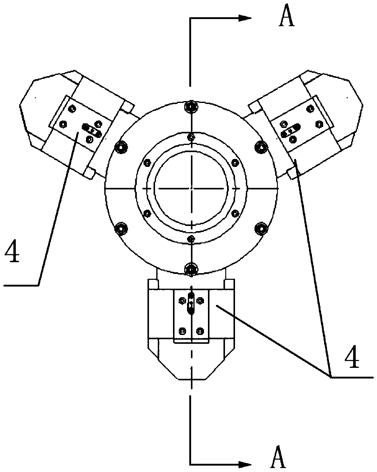
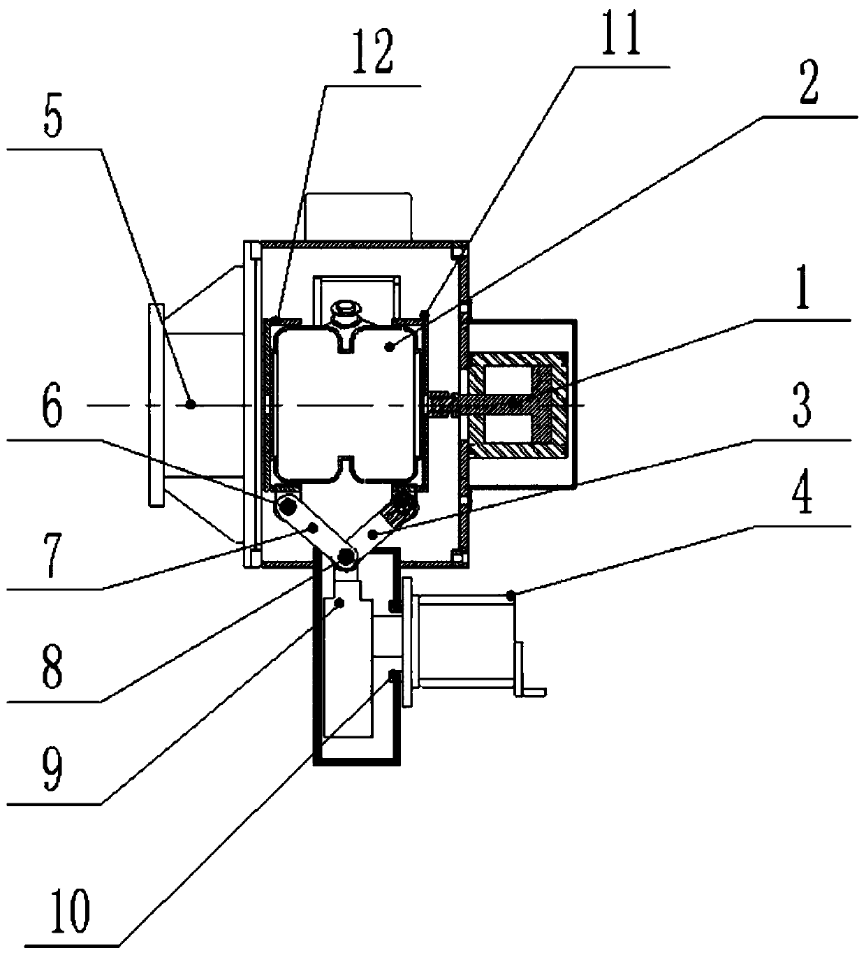
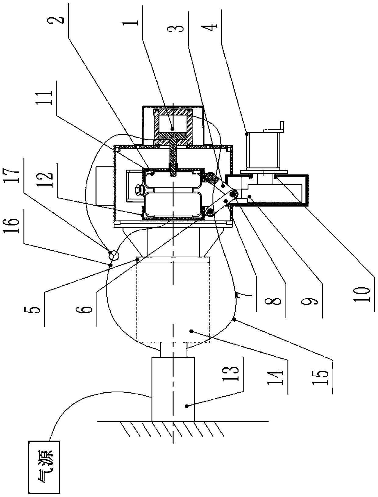
[0030] figure 1 It is the front view of the fixture in Embodiment 1 of the present invention; figure 2 The clamp provided for the present invention is along the figure 1 Sectional view of plane A-A in the center; image 3 It is a diagram of the working state of the fixture in Example 1 of the present invention when the workpiece is replaced. Such as figure 1 , figure 2 and figure 2 As shown, Embodiment 1 of the present invention provides a clamp, which includes a body, a cylinder assembly 1 , an airbag 2 , a reversing transmission device, a clamping assembly, an airbag top plate 11 and an airbag base 12 . The body is provided with an airbag 2 and a cylinder assembly 1, and a number of reversing transmission devices and a number of clamping assemblies are arranged on the circumference of the body. Any clamping assembly is connected to the airbag top plate 11 and the airbag base through the corresponding reversing transmission device 12 connections.

[0031] In this em...


PUM


Abstract

The invention relates to the technical field of clamping equipment and discloses a clamp which comprises a clamp body, wherein an air sac and an air cylinder assembly are arranged on the clamp body; aplurality of reversing transmission devices and a plurality of clamping components are arranged in the circumferential direction of the clamp body; an air sac top plate and an air sac base are arranged at the two ends of the air sac separately; any clamping component is connected with the air sac top plate and the air sac base through a corresponding reversing transmission device; a piston rod inthe air cylinder assembly is connected with the air sac top plate; the air sac top plate and the air sac base move relatively; the piston in the air cylinder assembly divides the air cylinder into afirst air chamber and a second air chamber; and the first air chamber, the second air chamber and the air sac communicate with an air source. Compared with the prior art, the clamp has the following benefits: the clamp adopts a linkage mechanism in which the air sac is matched with the air cylinder to obviously reduce the boundary dimension of the clamp; during the high speed rotation process, theclamp can prevent abrasive material and abrasive liquid from splashing; and the clamp also adopts a pneumatic rotary joint to enable air supply to be safe and stable.

Description

technical field [0001] The invention relates to the technical field of clamping equipment, in particular to a clamp. Background technique [0002] For a long time, fixtures have been widely used in the field of machining and manufacturing. Using excellent fixtures can process workpieces better, and can also keep the yield rate of processed workpieces at a high level. Today, with the rapid development of the electromechanical field, higher requirements are placed on fixtures, which need to be well suited for high-speed machining conditions. However, clamps with locking mechanisms currently on the market still cannot meet the above requirements, and their use is often limited. [0003] Taking the fixture disclosed in the utility model patent with the patent application number of 201120093673.8 as an example, the fixture uses a locking cylinder to drive a parallelogram mechanism to lock the workpiece, although it solves the problem of loosening and shifting of machined parts c...

Claims


Application Information

Patent Timeline
Patent Type & Authority Applications(China)
IPC IPC(8): B24B41/06
CPCB24B41/06
Inventor 类衍明刘国涛吕彤黄圆刘丰瑞杨雨林
Owner LANGFANG NORTH TIANYU ELECTROMECHANICAL TECH
Learn More