Vehicle differential speed reduction device for multi-motor control, differential mechanism and vehicle

A deceleration device and multi-motor technology, applied in control devices, vehicle parts, transportation and packaging, etc., can solve problems affecting the reliability of the power system, gravity bias of differential speed reducer, large volume and weight, etc., and achieve novel design , improve reliability, and improve the effect of cruising range

Pending Publication Date: 2019-11-22
杨小丽
View PDF0 Cites 0 Cited by
  • Summary
  • Abstract
  • Description
  • Claims
  • Application Information

AI Technical Summary

Problems solved by technology

However, due to the large power, volume and weight of the driving motor required by electric vehicles, it will form a gravity bias on the differential speed reducer, which will seriously affect the reliability of the power system. The reducer and the axle are combined together, but the method of splitting and setting the drive shaft and universal joint has to be adopted, which becomes an obstacle to upgrade the integrated technology of the motor, reduction differential, and axle

Method used


Image

  • Vehicle differential speed reduction device for multi-motor control, differential mechanism and vehicle
  • Vehicle differential speed reduction device for multi-motor control, differential mechanism and vehicle
  • Vehicle differential speed reduction device for multi-motor control, differential mechanism and vehicle

Examples


Embodiment Construction

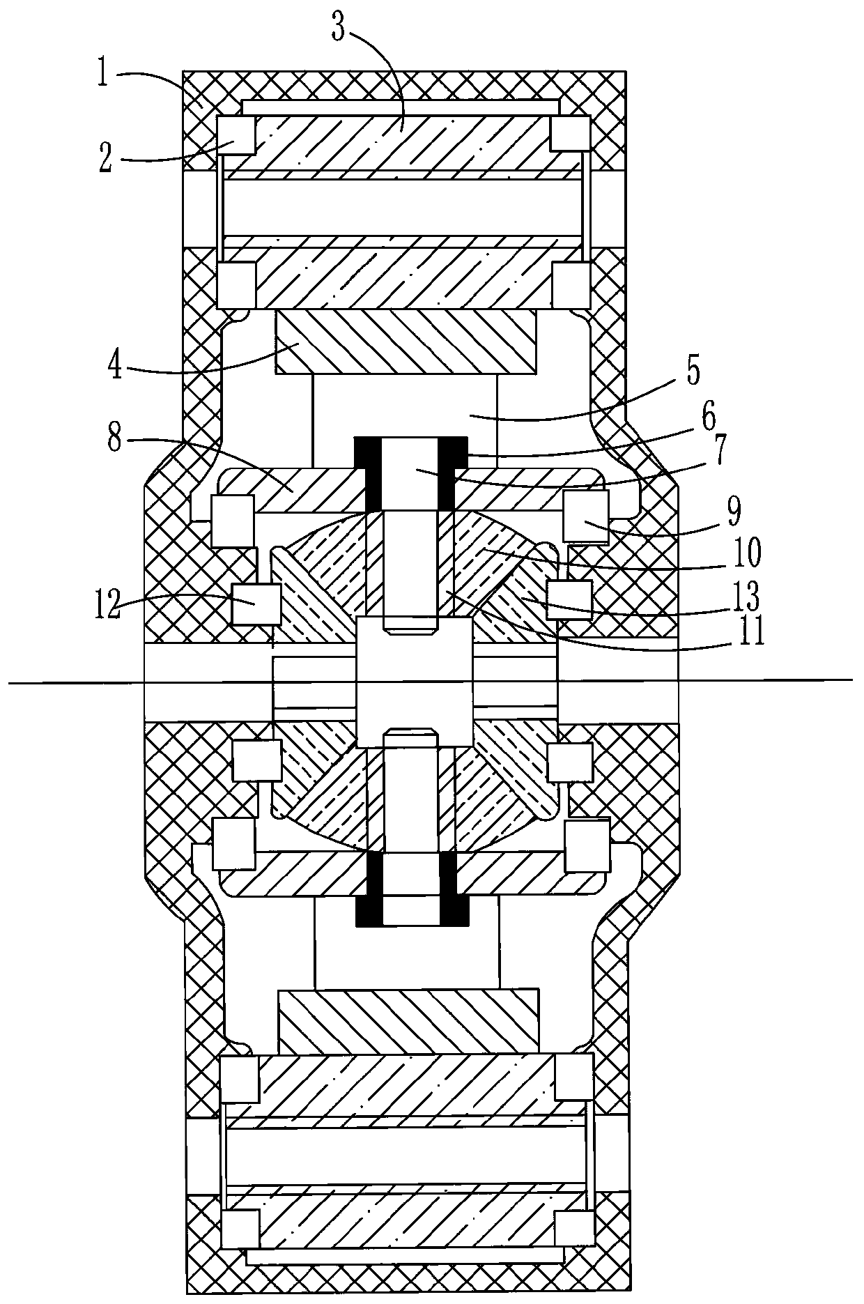
[0024] figure 1 Middle: Number 1 stands for housing, Number 2 stands for input gear bearing, Number 3 stands for input gear, Number 4 stands for passive ring gear, Number 5 stands for cross bracket of passive ring gear, Number 6 stands for pin sleeve, Number 7 stands for pin of planetary bevel gear , the number 8 represents the fixed ring of the planetary bevel gear, the number 9 represents the bearing of the fixed ring of the planetary bevel gear, the number 10 represents the planetary bevel gear, the number 11 represents the needle roller bearing, the number 12 represents the side shaft gear bearing, and the number 13 represents the side shaft gear;

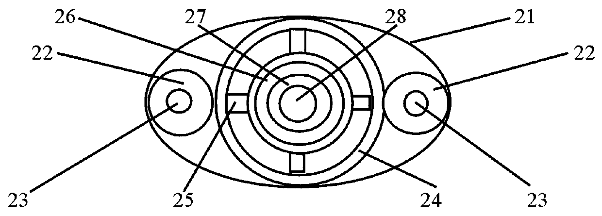
[0025] figure 2 Middle: The number 21 represents the housing, the number 22 represents the input gear, the number 23 represents the input gear hole, the number 24 represents the passive ring gear, the number 25 represents the cross bracket, the number 26 represents the fixed ring of the planetary bevel gear, and the number 27 ...


PUM


Abstract

The invention relates to the technical field of vehicle driving force transmission, in particular to a vehicle differential speed reduction device used for providing power for multiple motors, a differential mechanism and a vehicle. The device comprises a shell and a transmission gear set; the transmission gear set comprises the following parts: two input gears which are arranged on the two sidesof a middle shaft of the shell respectively; a driven gear ring clamped by the two input gears, and the outer tooth surface of the driven gear ring is meshed with the outer tooth surfaces of the inputgears; a planetary bevel gear fixing ring, wherein the outer diameter of the planetary bevel gear fixing ring is rigidly connected with the inner diameter of the driven gear ring through a cross bracket; four planetary bevel gears that are uniformly distributed on the planetary bevel gear fixing ring and rotate along with revolution of the planetary bevel gears; and two half axle gears used for clamping a planetary bevel gear set composed of the four planetary bevel gears and meshed with the planetary bevel gears. The input gears are symmetrically arranged on the two sides of the mounting position of the half axle of the vehicle and driven by the multiple motors, and balance and reliability of power transmission performance are guaranteed.

Description

technical field [0001] The invention relates to the technical field of vehicle driving force transmission, in particular to a vehicle differential speed reduction device, a differential gear and a vehicle used for multi-motor power supply. Background technique [0002] Electric vehicles generally adopt a power transmission method consisting of a central motor, a differential reducer, a half shaft, and a driving wheel. This method has mature technology and high reliability. Most electric vehicles at home and abroad adopt this technical solution. However, since the power required by various types of electric vehicles ranges from tens of kilowatts to hundreds of kilowatts, the supporting drive motors must have many specifications and varieties to cover different vehicles from small to large, and some specifications and varieties are due to demand. Less, it is difficult to form large-scale production. And because the drive motor, differential reducer, and axle can be combined i...

Claims


Application Information

Patent Timeline
Patent Type & Authority Applications(China)
IPC IPC(8): B60K17/08B60K17/16
CPCB60K17/08B60K17/165
Inventor 韩建方
Owner 杨小丽
Why Eureka
Try Eureka