
Powder material tank with automatic discharging

An automatic unloading and material tank technology, which is applied in the direction of conveying bulk materials, conveyors, containers, etc., can solve the problems of poor manual operation safety, long unloading time of semi-trailer tanks, and large surplus materials, so as to save manpower, Energy saving, environmental protection, unloading time and high degree of automation

Pending Publication Date: 2019-11-22
浙江超宇汽车科技有限公司
View PDF0 Cites 8 Cited by
  • Summary
  • Abstract
  • Description
  • Claims
  • Application Information

AI Technical Summary

Problems solved by technology

[0003] The invention provides an automatic unloading powder material tank, which aims to solve the problems of long unloading time of the semi-trailer tank body, large amount of residual material, and poor safety of manual operation in the prior art

Method used


Image

  • Powder material tank with automatic discharging
  • Powder material tank with automatic discharging
  • Powder material tank with automatic discharging

Examples


Embodiment 1

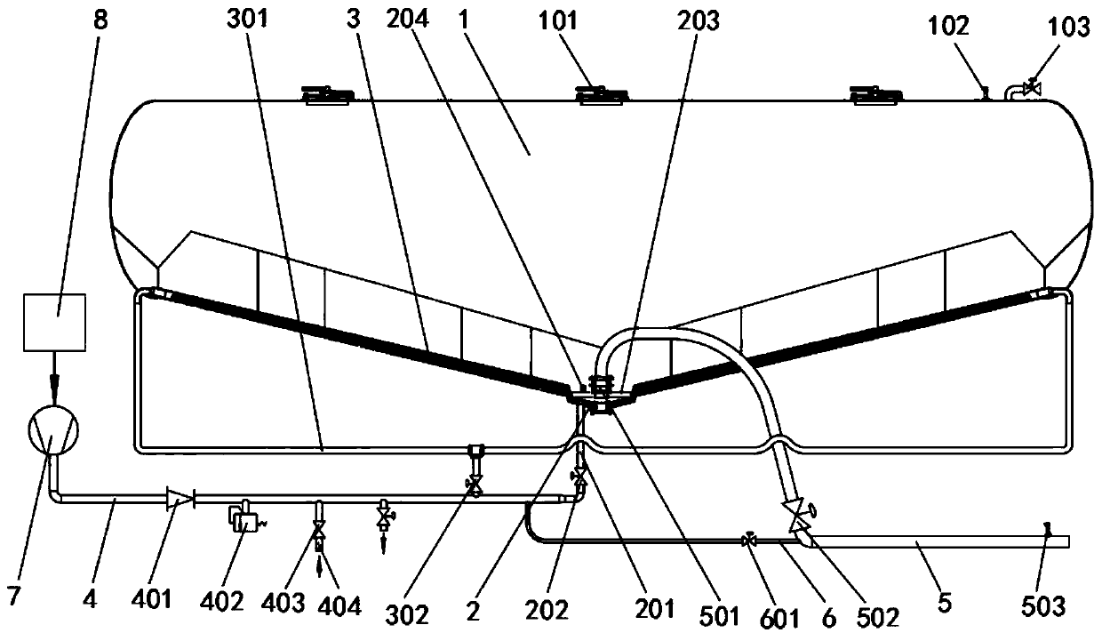
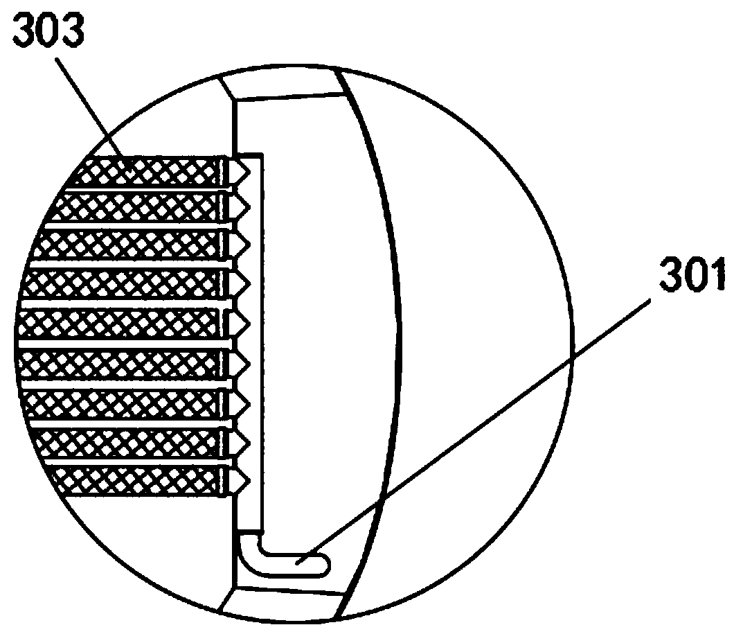
[0029] Such as Figure 1-3 Shown: an automatic unloading powder material tank, including a tank body 1 and a controller 8, a number of feeding holes 101 and pressure sensors 102 are arranged on the top of the tank body 1, and a main flow is arranged in the center of the bottom of the tank body 1 Bed 2, auxiliary fluidized bed 3 is arranged on both sides of main fluidized bed 2, auxiliary fluidized bed 3 extends from both ends of tank 1 to main fluidized bed 2 and slopes downward, main fluidized bed 2 passes through main fluidized bed Trachea 201 is connected with total intake pipe 4, main intake pipe 201 is provided with main intake valve 202, auxiliary fluidized bed 3 is connected with total intake pipe 4 through auxiliary intake pipe 301, auxiliary intake pipe 301 is provided with auxiliary intake valve 302, The main air intake pipe 4 is connected to the air compressor 7, and the air compressor 7 is connected to the controller 8. The top of the mainstream fluidized bed 2 is ...

Embodiment 2

[0032] Such as Figure 4 As shown, in the same tank 1, two sets of settings such as the main fluidized bed 2 and the auxiliary fluidized bed 3 in Embodiment 1 are adopted, and corresponding pipelines, valves and material sensors are set, which can further shorten the unloading time and improve unloading efficiency.

Embodiment 3

[0034] Such as Figure 5 As shown, in the same tank 1, three groups are adopted such as the setting of the main fluidized bed 2 and the auxiliary fluidized bed 3 in embodiment 1, and corresponding pipelines, valves and material sensors are set, which can further shorten the unloading time and improve unloading efficiency.


PUM


Abstract

The invention discloses a powder material tank with automatic discharging, and belongs to the technical field of a semi-trailer material tank. The powder material tank with the automatic discharging comprises a tank body and a controller. A plurality of feeding holes and a pressure sensor are arranged at the top of the tank body. The powder material tank with the automatic discharging is characterized in that a main fluidized bed is arranged in the center of the bottom of the tank body, and auxiliary fluidized beds are arranged on both sides of the main fluidized bed. The auxiliary fluidized beds extend from both ends of the tank body to the main fluidized bed and incline downward, the main fluidized bed is connected with a total air inlet pipe through a main air inlet pipe, the main air inlet pipe is provided with a main air inlet valve, the auxiliary fluidized beds are connected to the total air inlet pipe through auxiliary air inlet pipes, the auxiliary air inlet pipes are providedauxiliary air inlet valves, the total air pipe is connected to an air compressor, the air compressor is connected with the controller, a perforated plate is arranged on the upper part of the main fluidized bed, the perforated plate is provided with a level sensor and a discharging tube, and the discharge tube is provided with a discharging valve and a flow sensor. The discharging efficiency is greatly improved, labor is reduced, energy is saved, and the environment is protected.

Description

technical field [0001] The invention relates to the technical field of semi-trailer material tanks, in particular to an automatic unloading powder material tank. Background technique [0002] Semi-trailer tank trucks for powder materials have been unloading manually for decades. It has been used in China for more than 60 years. The tank structure is unified (single V, double V, triple V) fluidized bed, sliding plate Air chamber etc. The outside of the tank is composed of main air pipe, discharge pipe and manual valve. According to the description of (single V) semi-hanging tank, the basic structure of a manual discharge valve and main air valve cannot control the material and air during the discharge process. The fluidized density after mixing is high, and there is a lot of residual material after unloading at the same time. Manual operation is prone to accidents (the operator's hands are burned by high temperature). The biggest problem is the long unloading time. The main ...

Claims


Application Information

Patent Timeline
IPC IPC(8): B65D88/72B65G53/66
CPCB65D88/72B65G53/66B65G2201/042
Inventor 张思杭
Owner 浙江超宇汽车科技有限公司
Learn More