
Suction nozzle rotating mechanism

A technology of a rotating mechanism and a rotator, which is applied to conveyor objects, transportation and packaging, etc., can solve the problem of inability to put parts into the casing, and achieve the effects of simple structure, reduced horizontal area, and convenient use.

Pending Publication Date: 2019-11-22
SUZHOU RS TECH
View PDF0 Cites 0 Cited by
  • Summary
  • Abstract
  • Description
  • Claims
  • Application Information

AI Technical Summary

Problems solved by technology

[0003] In the field of assembly, for box-shaped workpieces, when the parts are assembled inside the box body, the size of the internal parts is the same as that of the shell workpiece, and the mounting opening on the shell is smaller than the parts, so that it is impossible to use general assembly equipment. Components are put into the shell. When such a station appears, it needs to be assembled manually. It is a huge challenge for the automation of the assembly line.

Method used


Image

  • Suction nozzle rotating mechanism
  • Suction nozzle rotating mechanism
  • Suction nozzle rotating mechanism

Examples


Embodiment Construction

[0029] The present invention will be further described in detail below with reference to the accompanying drawings. The foregoing and other objectives, features, aspects and advantages of the present invention will become more apparent, so that those skilled in the art can implement them with reference to the text of the description. In the drawings, the shape and size may be enlarged for clarity, and the same reference numerals will be used in all the drawings to indicate the same or similar parts. In the following description, terms such as center, thickness, height, length, front, back, rear, left, right, top, bottom, upper, and lower parts are based on the orientation or positional relationship shown in the drawings. In particular, "height" corresponds to the size from top to bottom, "width" corresponds to the size from left to right, and "depth" corresponds to the size from front to back. These relative terms are for convenience of description and are generally not intende...


PUM


Abstract

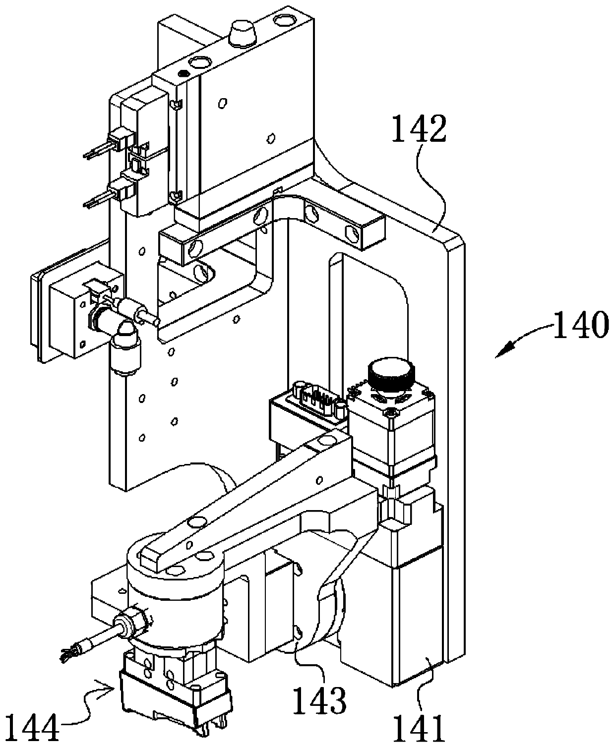
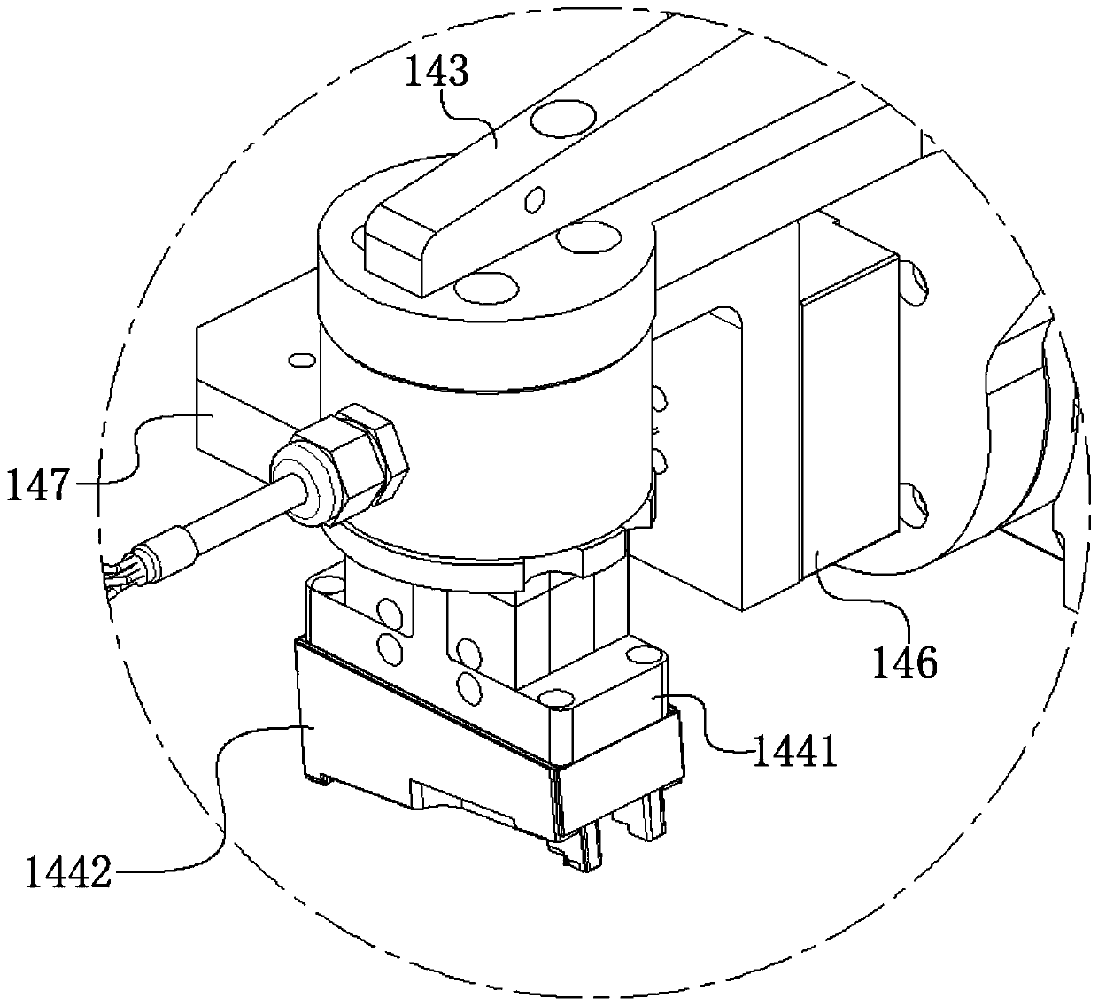
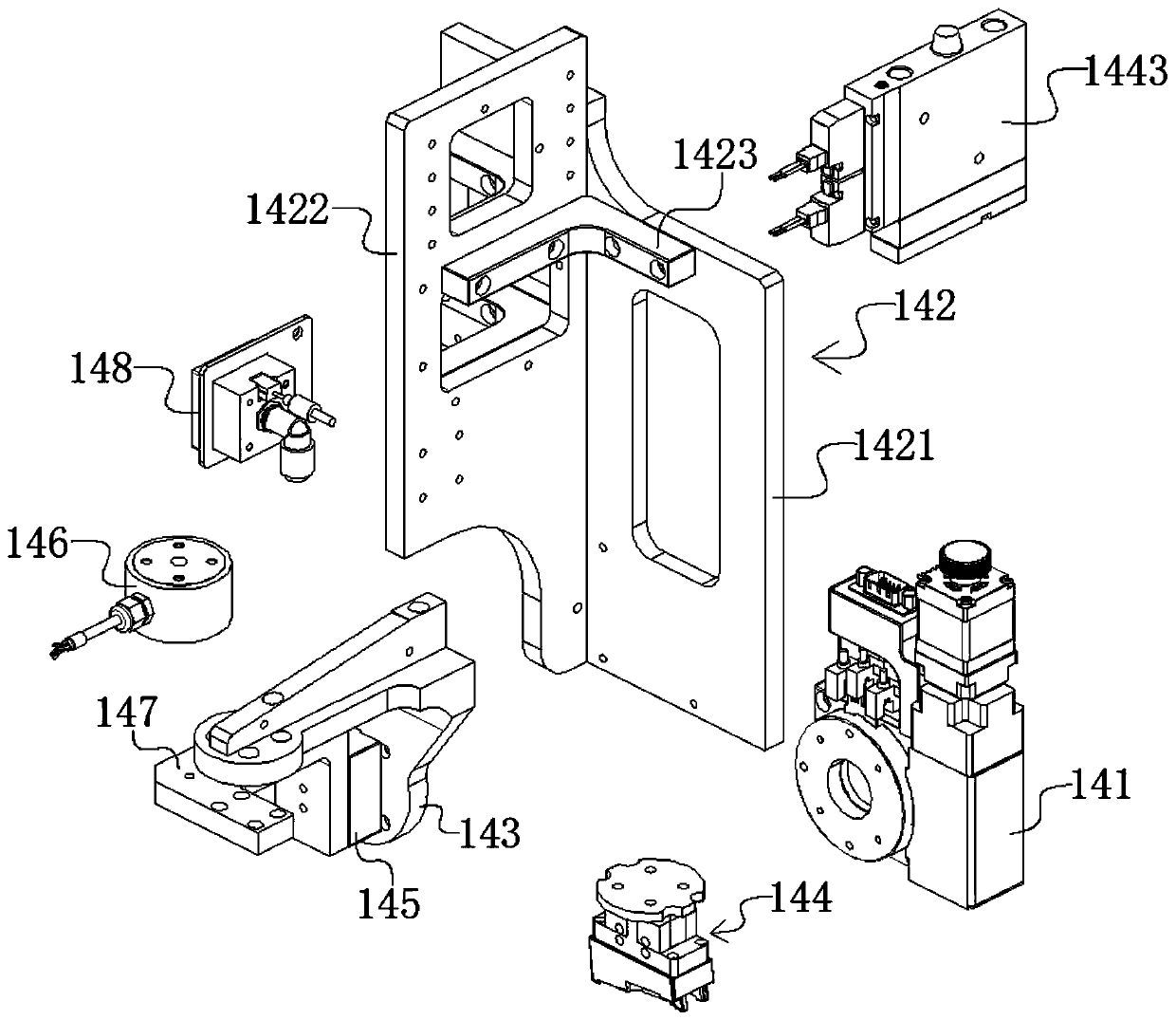
The invention discloses a suction nozzle rotating mechanism. The suction nozzle rotating mechanism comprises a rotating suction nozzle assembly, wherein the rotating suction nozzle assembly comprisesa rotator and a suction nozzle unit; the rotator is connected with the suction nozzle unit; the rotator is a rotating sliding table; and the suction nozzle unit comprises a suction nozzle block, a working block and a vacuum generator. Through the working of the vacuum generator, the working block generates a negative pressure through the suction nozzle block to suck a workpiece; a groove which issimilar to the contour of the workpiece is formed in the working block, so that the workpiece is conveniently matched with the working block and convenient to replace; the rotating device drives the suction nozzle block to rotate to enable the workpiece to rotate within a certain angle; the workpiece is inclined to conveniently stretch into a mounting hole which is smaller than the length of the workpiece; and the suction nozzle rotating mechanism is simple in structure and convenient for realizing automatic assembly of the workpiece.

Description

Technical field [0001] The invention belongs to the field of assembly equipment, and specifically relates to a suction nozzle rotating mechanism. Background technique [0002] In automated production, fixtures are often used to clamp the workpiece. In order to prevent the workpiece from being displaced after being forced during the processing, the processing accuracy is low. At the same time, the workpiece can be positioned by the fixture and the workpiece is placed on the processing position. The assembly line is very extensive in order to achieve automation. [0003] In the assembly field, for box-shaped workpieces, when assembling parts inside the box, the size of the internal parts is the same as that of the shell workpiece, and the mounting openings on the shell are smaller than the parts, making it impossible to use general assembly equipment The components are placed in the housing. When such a work station appears, it needs to be assembled manually, which is a huge challen...

Claims


Application Information

Patent Timeline
IPC IPC(8): B65G47/91
CPCB65G47/915
Inventor 吴加富缪磊马纪飞李启强文太平马伟
Owner SUZHOU RS TECH
Learn More