Treatment structure of high-water-level soft soil bridgehead roadbed and construction method

A construction method and high water level technology, applied in infrastructure engineering, soil protection, roads, etc., can solve problems such as unsatisfactory results of treatment measures, difficulties in construction quality control, treatment of deformed and compressed layers, etc., and achieve control of subgrade differences Settlement, solve the problem of jumping at the bridge head, and reduce the effect of self-weight

Pending Publication Date: 2019-11-22
CHINA MERCHANTS CHONGQING COMM RES & DESIGN INST
View PDF0 Cites 2 Cited by
  • Summary
  • Abstract
  • Description
  • Claims
  • Application Information

AI Technical Summary

Problems solved by technology

[0004] However, if the thickness of the soft foundation is relatively large (thickness reaches 50-60m) and the groundwater level is relatively high, according to theory, the deformed compression layer (the stratum with additional stress less than or equal to 0.1 times the self-weight stress) is relatively thick, and the treatment of the transition section of the bridgehead should be set. It is difficult to implement this method in this environment, and conventional treatment measures such as: drainage consolidation body + surcharge preloading, powder jetting piles, high-pressure rotary jetting piles, prestressed pipe piles, etc., are also impossible to completely remove the deformed compression layer. Therefore, in actual construction, it is often only possible to deal with 0.3-0.6 times the thickness of the compressed layer. In addition, it is difficult to control the construction quality. After completion, there will still be a large amount of post-construction settlement, resulting in serious bridge head jumping.
[0005] Therefore, none of the existing treatment measures can achieve satisfactory results for the anti-differential settlement treatment of such high-water level soft foundation bridge head subgrades.

Method used


Image

  • Treatment structure of high-water-level soft soil bridgehead roadbed and construction method
  • Treatment structure of high-water-level soft soil bridgehead roadbed and construction method
  • Treatment structure of high-water-level soft soil bridgehead roadbed and construction method

Examples


Embodiment Construction

[0049] Embodiments of the technical solutions of the present invention will be described in detail below in conjunction with the accompanying drawings. The following examples are only used to illustrate the technical solutions of the present invention more clearly, and therefore are only examples, rather than limiting the protection scope of the present invention. In the description of the present application, it should be understood that the orientation or positional relationship indicated by the terms "upper", "lower", "front", "rear", "left", "right" etc. is based on the drawings The orientation or positional relationship shown is only for the convenience of describing the present invention and simplifying the description, but does not indicate or imply that the components or structures referred to must have a specific orientation, be constructed and operated in a specific orientation, and therefore cannot be construed as limiting the scope of the present invention. limit. ...


PUM


Abstract

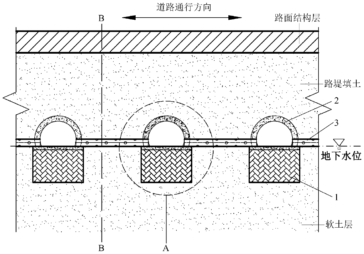
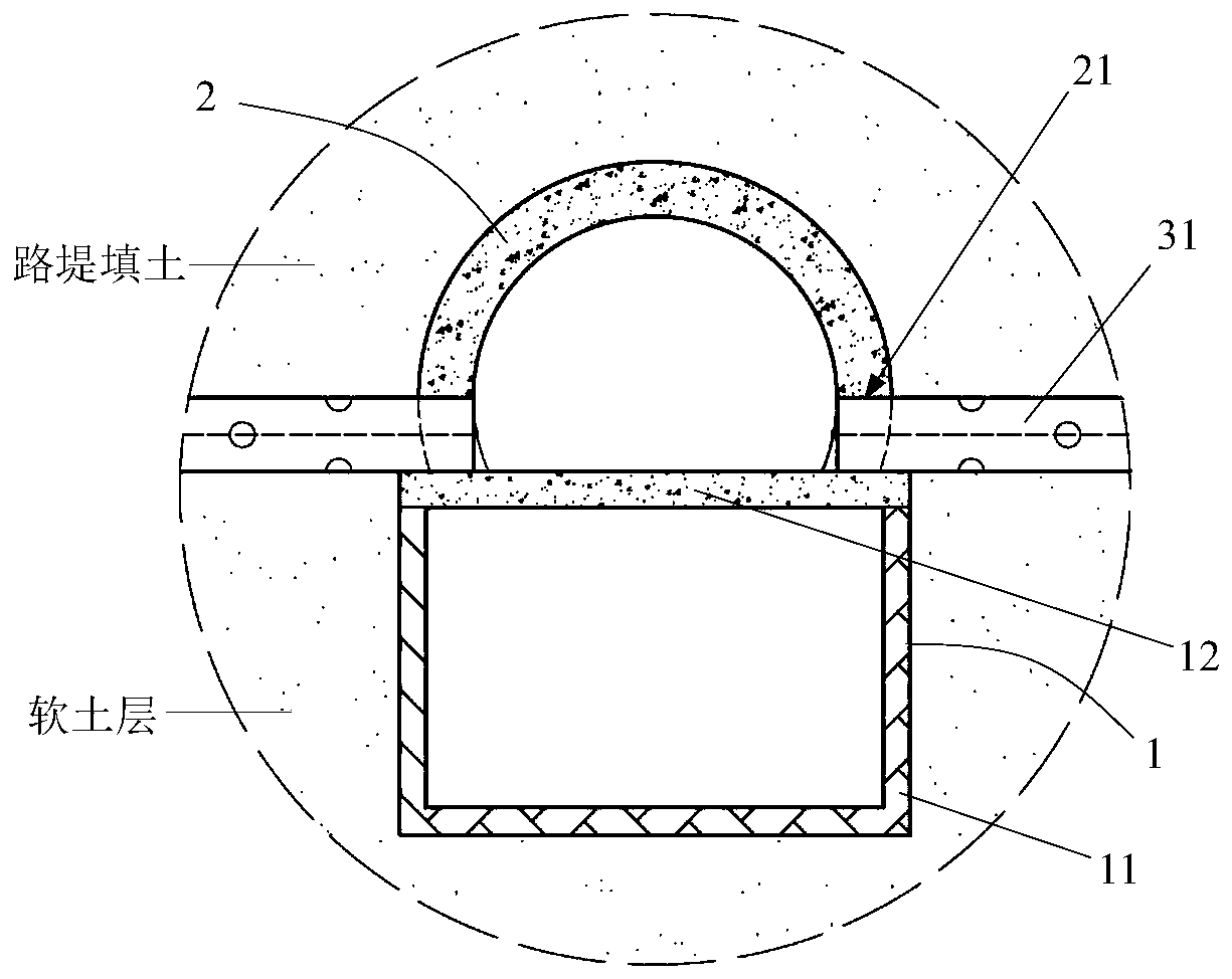
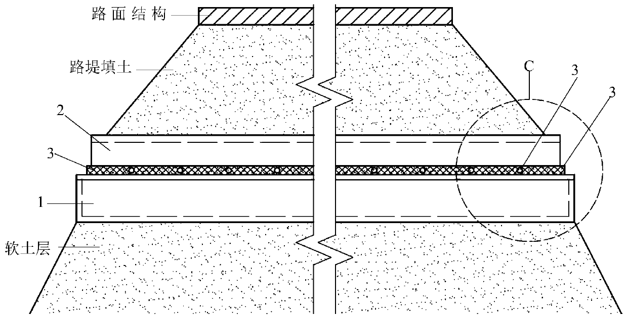
The invention discloses a treatment structure of a high-water-level soft soil bridgehead roadbed that comprises buoyancy bodies that are arranged below the underground water level of a soft soil layerand are made of waterproof materials with the volume density not larger than 1.0 g / cm < 3 >, wherein the multiple buoyancy bodies are arranged in the passing direction of a road at intervals, and each buoyancy body is horizontally arranged in the width direction of the road; the upper portion of each buoyancy body is provided with one jacking pipe, the jacking pipes and the buoyancy bodies are horizontally arranged in the same direction, each jacking pipe is of a half-pipe structure with an opening in one side, and the openings of the jacking pipes are buckled to the upper surfaces of the buoyancy bodies; and a rigid connecting body is connected between the two adjacent jacking pipes. According to the treatment structure, a corresponding using method is adopted, differential settlement ofhigh-water-level soft foundation bridgehead roadbeds of a newly-built road and an existing road can be effectively treated, and the problem of bridgehead bumping caused by differential settlement issolved.

Description

technical field [0001] The invention relates to the technical field of anti-subsidence treatment of deep and thick soft ground strata in civil engineering, in particular to a treatment structure and construction method of high-water level soft soil bridge head embankment. Background technique [0002] In areas with deep soft foundations, the soil layer usually has the characteristics of high compressibility, low strength, low permeability, slow consolidation, and high sensitivity. When building roads on this basis, if effective measures are not taken for the underlying soft For treatment, under the action of the embankment load on it, the soft soil layer is consolidated and compressed, resulting in a large settlement, which has a great impact on the safety and comfort of the later operation. [0003] Especially in the subgrade section at the bridge head, because the bridge pile foundation is often supported on the hard bearing layer below it, no settlement will occur after c...

Claims


Application Information

Patent Timeline
Patent Type & Authority Applications(China)
IPC IPC(8): E01C3/04E02D3/12E02D3/10
CPCE01C3/04E02D3/10E02D3/12E02D2250/003
Inventor 马小斐张东长李海平阎宗岭徐建强苟栋元王洋刘朝辉付玉
Owner CHINA MERCHANTS CHONGQING COMM RES & DESIGN INST
Why Eureka
Try Eureka