Electronic lock

A technology of electronic locks and lock housings, which is applied in the field of electronic locks, can solve the problems of easy-wearing transmission parts, over-turning knobs, dislocation and dislocation of transmission parts, etc., and achieve low wear rate of transmission parts, precise transmission process and few transmission parts Effect

Pending Publication Date: 2019-11-22
陈海英
View PDF1 Cites 3 Cited by
  • Summary
  • Abstract
  • Description
  • Claims
  • Application Information

AI Technical Summary

Problems solved by technology

However, the design of this structure is simple and rough, and its knob shaft and stroke swing arm are single-point transmission and single-point contact positioning structures, which have the following defects: (1) The transmission contact is single-point contact, which makes the transmission more laborious and is easy to be damaged by the motor. Excessive transmission inertia causes dislocation and dislocation of the transmission parts; (2) it i

Method used


Image

  • Electronic lock
  • Electronic lock
  • Electronic lock

Examples


Embodiment 1

[0034] In this embodiment, the inside of the door is an electronic lock that opens to the right.

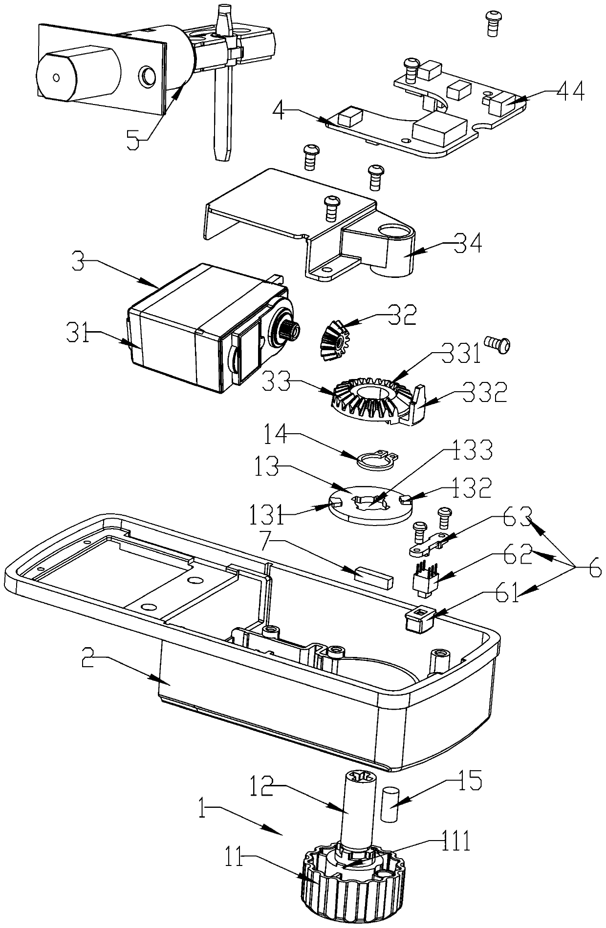
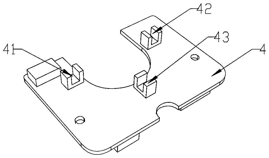
[0035] Such as figure 1 , an electronic lock, comprising: a knob mechanism 1, a lock case 2, a transmission mechanism 3, a control board 4, and a bolt mechanism 5.

[0036] Such as figure 1 with 4 , the knob mechanism 1 includes a knob 11 , a knob shaft 12 , and a knob linkage 13 . The knob 1 is located on the outside of the lock case 2 . The knob shaft 12 is connected to the inner side of the knob 11, and the knob 11 vertically extends into the anti-lock shaft hole 21 on the lock housing 2 and extends into the inner side of the lock housing 2; It can drive the extension or retraction of the dead bolt mechanism 5. The knob linkage 13 is provided with a linkage through hole 133, and the linkage through hole 133 is sleeved on the knob shaft 12 and compressed by the circlip 14; the knob linkage 13 can rotate synchronously with the knob shaft 12 . The knob linkage 13 is provid...

Embodiment 2

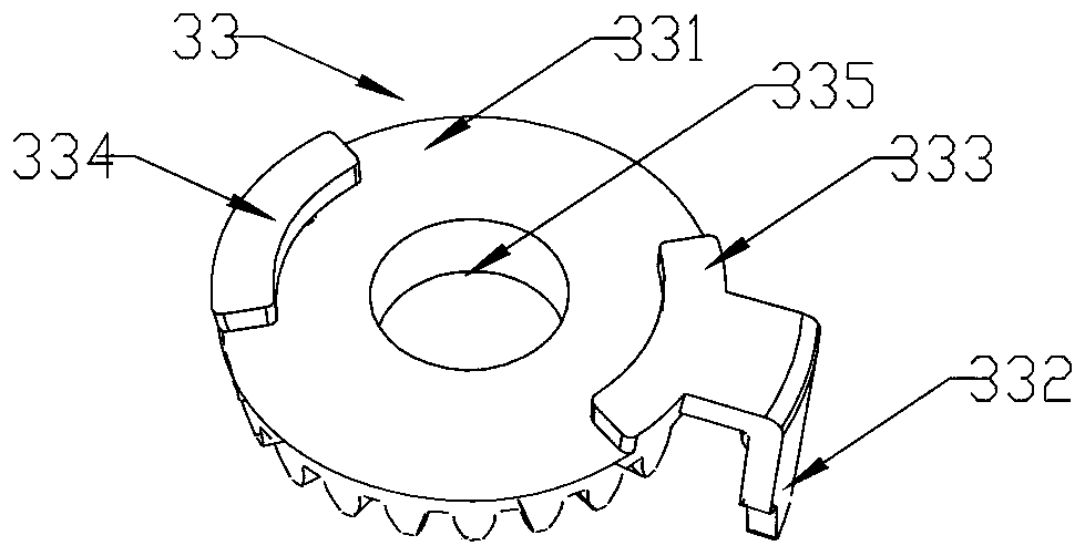
[0048] Such as Figure 10-13 , the present embodiment is the action process of opening the electronic lock from the left. The difference between this embodiment and Embodiment 1 is that there is no need to replace any parts, only need to adjust the control program of the main control panel 4, and adjust the relative relationship between the knob linkage 13 and the driven gear plate 33 in the initial state (normally open state). location, such as Figure 10 (c). Its locking, unlocking, and control principles are consistent with Embodiment 1.

[0049] Such as Figure 11 , the knob 11 is turned 90° clockwise to realize locking; the locking of the knob does not drive the rotation of the transmission mechanism 3 .

[0050] Such as Figure 12 , the driven gear plate 33 rotates 90° clockwise to realize unlocking; the rotation of the speed change transmission mechanism 3 will drive the knob 11 to rotate synchronously;

[0051] Such as Figure 13 , the driven gear plate 33 rotat...


PUM


Abstract

The invention provides an electronic lock which comprises a lock shell, a bolt mechanism, a control main board, a rotary knob mechanism and a variable speed transmission mechanism. The rotary knob mechanism comprises a rotary knob linkage part rotating synchronously with a rotary knob. The variable speed transmission mechanism comprises a driven gear disc arranged coaxially with the rotary knob linkage part. A gear disc body is provided with a first gear disc boss, a second gear disc boss, and a gear disc swing arm arranged vertically, wherein the first gear disc boss and the second gear discboss are arranged symmetrically. A first rotary knob boss and a second rotary knob boss are arranged on one side of the rotary knob linkage part and arranged symmetrically. Two symmetrical stroke tracks are formed between the first gear disc boss and the second gear disc boss. The first rotary knob boss and the second rotary knob boss are located on the two opposite stroke tracks correspondingly.The control main board is further provided with a first resetting induction switch, a second resetting induction switch and a resetting-in-place induction switch, wherein the first resetting inductionswitch and the second resetting induction switch are used for inducting the gear disc swing arm. The electronic lock has the advantages of being little in transmission disturbance, little in part abrasion and precise in transmission and resetting.

Description

technical field [0001] The invention relates to an electronic lock, in particular to an intelligent electronic lock with a single dead tongue. Background technique [0002] The traditional glass lock or mortise single tongue lock has a simple structure and is widely used; with the promotion of intelligent and convenient application of smart door locks, glass locks or mortise single tongue locks are gradually replacing electronic locks. [0003] Single-tongue locks generally only have a dead tongue. Most of the existing single-tongue electronic locks are driven by a motor to drive the gear plate, thereby driving the handle or the axis of the knob, and the linkage lock tongue is stretched and retracted to realize unlocking or locking. For example, the patent with the publication number CN204876878U structure. However, the design of this structure is simple and rough, and its knob shaft and stroke swing arm are single-point transmission and single-point contact positioning str...

Claims


Application Information

Patent Timeline
IPC IPC(8): E05B47/00E05B15/00E05B63/04
CPCE05B15/0013E05B15/004E05B47/0012E05B63/04E05B2047/002
Inventor 陈海英
Owner 陈海英
Why Eureka
Try Eureka