Park lock arrangement and vehicle comprising such park lock arrangement

A parking and equipment technology, applied in the field of vehicles, to achieve the effect of compact weight and compact installation

Inactive Publication Date: 2019-11-22
VOLVO CAR CORP
View PDF11 Cites 0 Cited by
  • Summary
  • Abstract
  • Description
  • Claims
  • Application Information

AI Technical Summary

Problems solved by technology

Such park lock devices generally function rela

Method used


Image

  • Park lock arrangement and vehicle comprising such park lock arrangement
  • Park lock arrangement and vehicle comprising such park lock arrangement
  • Park lock arrangement and vehicle comprising such park lock arrangement

Examples


Embodiment Construction

[0024] The embodiments of the invention with further developments described below are to be considered as examples only and in no way limit the scope of protection offered by the patent claims.

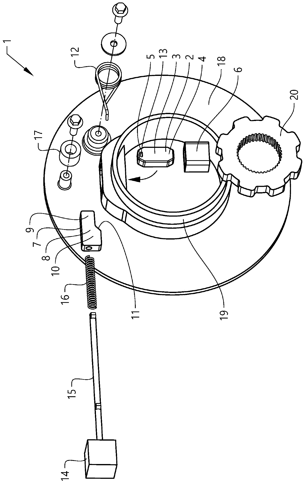
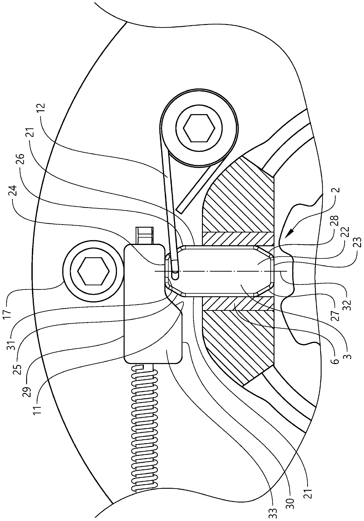
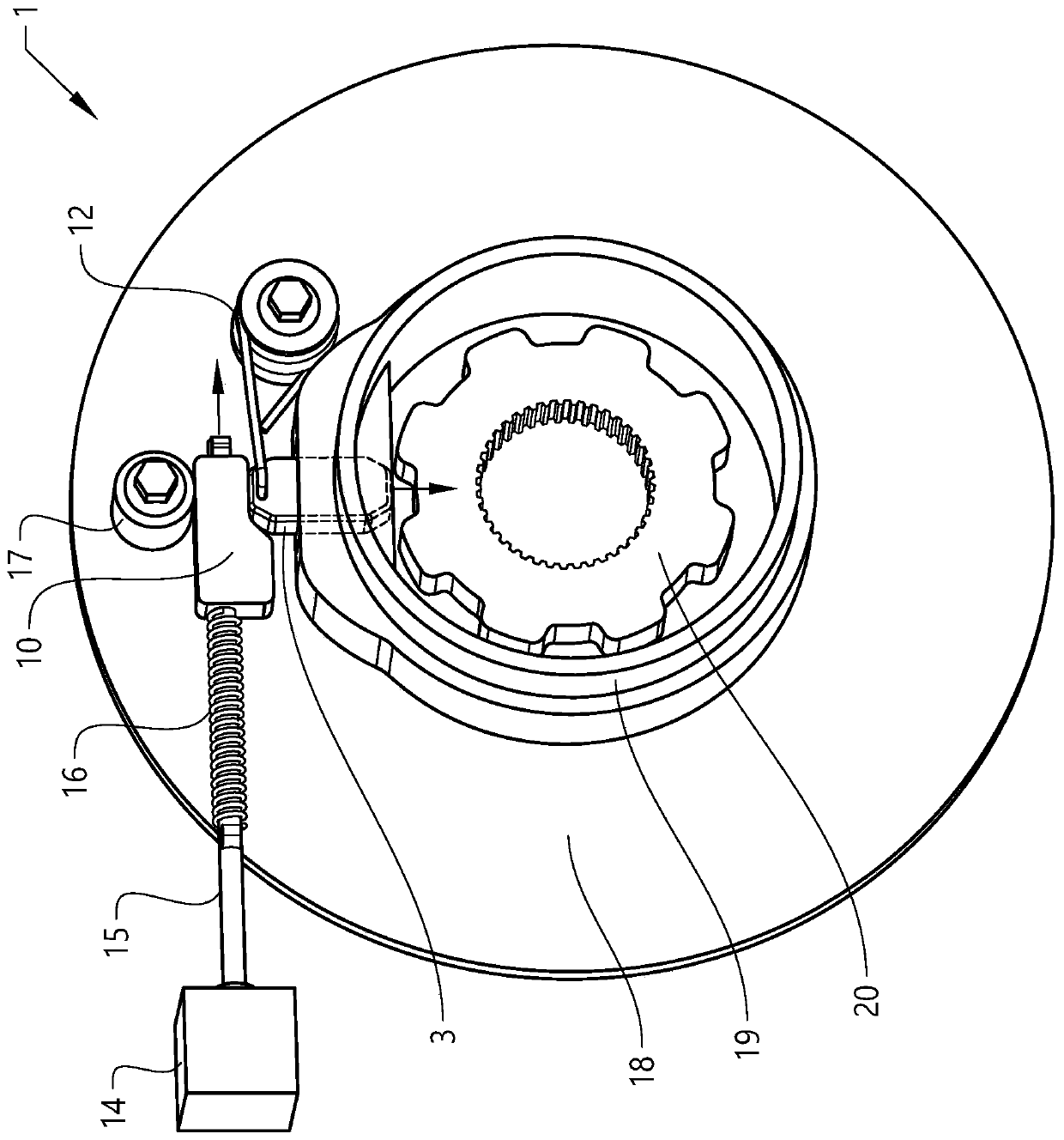
[0025] Figure 1 to Figure 4 shows the parking lock device of the present invention, and Figure 5 A vehicle including such a parking lock device is shown.

[0026] The parking lock device comprises a parking pawl 2 , an actuating device 7 and a return spring 12 . The parking pawl is arranged in such a image 3 The released position shown in , in which the park gear is free to rotate, or in a position such as Figure 4 The locked position shown in , in which the park gear is locked. The parking pawl 2 is adapted to slide between a released position and a locked position. In the example shown, the parking pawl is longitudinal, with a rectangular cross-section. The parking pawl comprises a body 3 having a locking end 4 and an actuating end 5 . The short side 21 of the body is ada...


PUM


Abstract

A park lock arrangement for a vehicle, including a park pawl, an actuating means, and a return spring, where the park pawl is arranged to be in either a release position or in a lock position, whereinthe park pawl is longitudinal and includes a body having a lock end and an actuation end, where the park pawl is arranged to slide between the release position and the lock position. The advantage ofthe invention is that a compact and cost-effective park lock arrangement with is provided.

Description

technical field [0001] The invention relates to a parking lock device for a vehicle and to a vehicle comprising such a parking lock device. The parking lock apparatus includes a slidable parking pawl adapted to slide between a released position to a locked position. Background technique [0002] A vehicle with an automatic transmission or an electric vehicle without a gearbox is provided with a parking lock function adapted to lock an output shaft of an automatic transmission or an output shaft of an electric motor, which restricts the vehicle from moving in any direction. The park pawl prevents the transmission from rotating, and thus prevents the vehicle from moving. The park pawl locks the output shaft of the transmission or the output shaft of the electric motor to the transmission case by engaging a pawl (pin) that engages with a park gear (notched wheel) disposed on the output shaft, making the output shaft of the transmission (and thus the driven wheel) stops spinni...

Claims


Application Information

Patent Timeline
IPC IPC(8): F16H63/34
CPCF16H63/3425F16H63/3433B60T1/005F16H63/3416F16H63/3466F16H63/3475
Inventor R·基西莱维茨
Owner VOLVO CAR CORP
Why Eureka
Try Eureka