
Air separation device

A technology of air separation and symmetrical arrangement, applied in the field of pressure equipment, which can solve the problems of increasing the transportation height of the rectification tower and increasing the upper tower of the rectification tower, and achieve the effect of reducing the number of packed trays, avoiding waste, and reducing the transportation height

Inactive Publication Date: 2019-11-22
LAIR LIQUIDE SA POUR LETUDE & LEXPLOITATION DES PROCEDES GEORGES CLAUDE
View PDF6 Cites 0 Cited by
  • Summary
  • Abstract
  • Description
  • Claims
  • Application Information

AI Technical Summary

Problems solved by technology

Sometimes the height of the upper tower of the rectification tower is increased due to the design of the opening of the dirty nitrogen gas. At the same time, the actual number of packing plates of the pure nitrogen tower is more than required due to the increase of the height of the upper tower of the rectification tower. The number of theoretical packed trays, resulting in an increase in the overall transport height of the rectification column (the upper column of the rectification column is usually transported together with the pure nitrogen column)

Method used

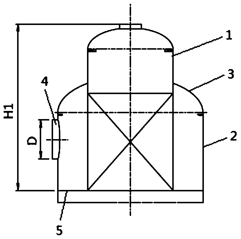
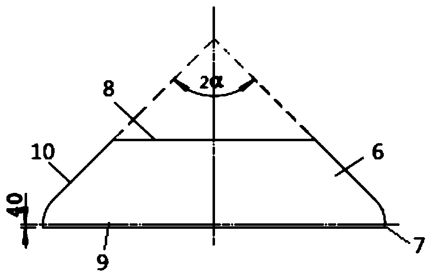
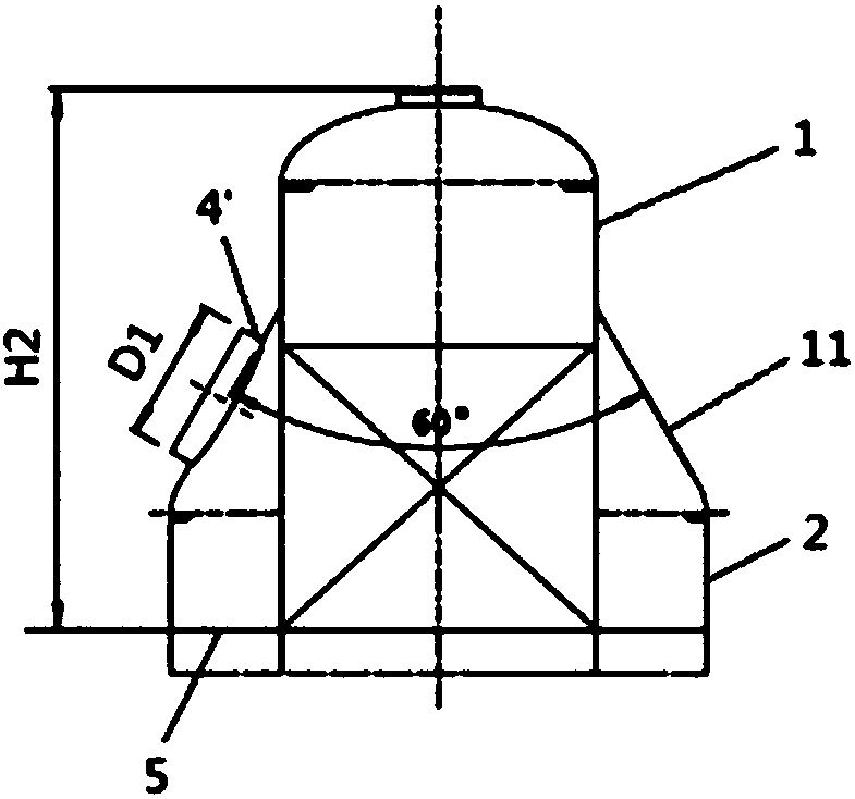

Image

  • Air separation device
  • Air separation device
  • Air separation device

Examples


Embodiment Construction

[0030] Specific embodiments of the present invention will be described in detail below in conjunction with the accompanying drawings. However, the present invention should be understood as not limited to such embodiments described below, and the technical idea of ​​the present invention can be implemented in combination with other known technologies or other technologies having the same functions as those known technologies.

[0031] In the following description of specific embodiments, it is to be understood that the terms "height", "upper", "lower", "front", "rear", "vertical", "horizontal", "top", "bottom" , "inner", "outer" and other indicated orientations or positional relationships are based on the orientations or positional relationships shown in the drawings, which are only for the convenience of describing the present invention and simplifying the description, rather than indicating or implying that the referred devices or elements must Having a particular orientation...


PUM


Abstract

The invention discloses an air separation device. The device at least comprises a rectifying tower, the rectifying tower comprises a first tower body and a second tower body, the first tower body is arranged on the second tower body, the diameter of the first tower body is smaller than that of the second tower body, the first tower body and the second tower body are connected through a conical seal head, and at least one open hole is formed in the conical seal head.

Description

technical field [0001] The invention belongs to the field of pressure equipment, and in particular relates to an air separation device. Background technique [0002] The head is an indispensable and important part of pressure vessel equipment in many industries from petrochemical, atomic energy, to food, pharmaceutical and so on. The head is an important part of the equipment. It is connected with the cylinder to form the shell of the equipment. The head and the cylinder can be directly welded to form a non-detachable connection. The advantage of this connection method is that the connection cost is low, The sealing performance is good, and the leakage accident in the production process is not easy to occur. [0003] As a part of the container, the head can be divided into spherical, oval, dish, spherical crown, conical shell and flat cover according to the geometric shape and different fields of application. The head is also collectively referred to as the convex head, wh...

Claims


Application Information

Patent Timeline
Patent Type & Authority Applications(China)
IPC IPC(8): F25J3/04
CPCF25J3/04896
Inventor 朱维波菲利普葛睿高莱多李群芳马爱兰
Owner LAIR LIQUIDE SA POUR LETUDE & LEXPLOITATION DES PROCEDES GEORGES CLAUDE
Learn More