
X-ray imaging detection system

An imaging detection and X-ray technology, applied in the direction of measuring devices, using wave/particle radiation, instruments, etc., to achieve the effect of multi-angle detection

Active Publication Date: 2019-11-22
俐玛精密测量技术(苏州)有限公司
View PDF10 Cites 0 Cited by
  • Summary
  • Abstract
  • Description
  • Claims
  • Application Information

AI Technical Summary

Problems solved by technology

[0007] However, none of the above detection systems can be directly used for the detection of workpieces with many angles to be detected.

Method used


Image

  • X-ray imaging detection system
  • X-ray imaging detection system
  • X-ray imaging detection system

Examples


Embodiment 1

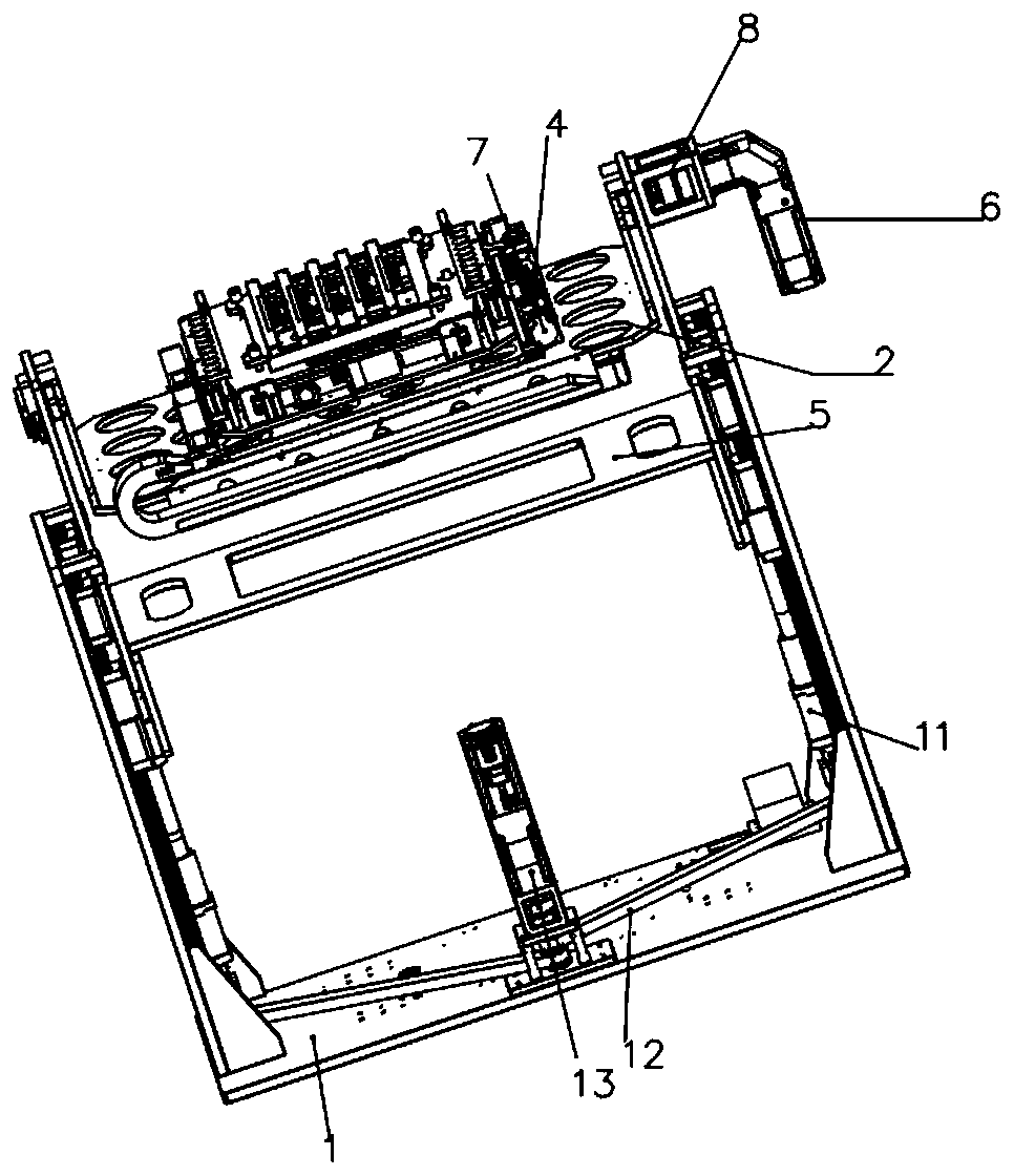
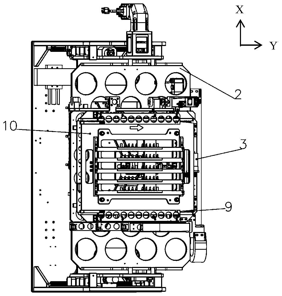
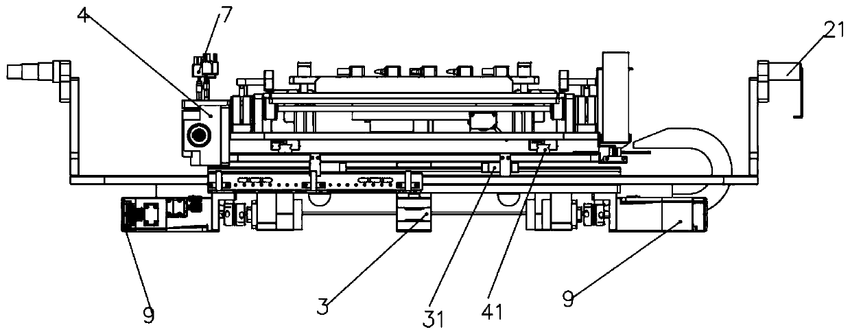
[0042] Such as Figure 1-5 As shown, the present invention provides an X-ray imaging detection system, which includes an X-ray emitting assembly and an X-ray receiving assembly 16, the X-ray emitting assembly includes an X-ray source, and the X-ray receiving assembly 16 includes an X-ray receiver 164, the X-rays emitted by the X-ray source are irradiated vertically downward and received by the X-ray receiver 164, and also include a rotating mechanism arranged between the X-ray emitting assembly and the X-ray receiving assembly to drive the workpiece to rotate , the rotating mechanism is fixed above the U-shaped fixed bracket 1,

[0043] The rotating mechanism includes a first base plate 2, a first screw mandrel 3, a second screw mandrel 4, a first motor 9, a second motor 7, a third motor 6 and a first coupling 8, and the first base plate is vertical a connection between the x-ray source and the x-ray receiver;

[0044]The first screw mandrel 3 and the second screw mandrel 4 ...


PUM


Abstract

The invention, which belongs to the technical field of image detection systems, particularly relates to an X-ray imaging detection system comprising an X-ray emitting assembly and an X-ray receiving assembly. The X-ray emitting assembly includes an X-ray source. The X-ray receiving assembly includes an X-ray receiver. An X ray emitted by the X-ray source is irradiated vertically and downwardly andis received by the X-ray receiver. The system also includes a rotating mechanism arranged between theX-ray emitting assembly and the X-ray receiving assembly. The rotating mechanismincludes a first substrate, a first lead screw, a second lead screw, a first motor, a second motor, a third motor, and a first coupler; the first substrate is provided with a rotating shaft; and the first coupler is connected to the rotating shaft. With the X-ray imaging detection system, the detection of the internal structure and size of the product can be realized; and the multi-angle detection of the workpiececan be realized by detecting the position and anglechanges in the process.

Description

technical field [0001] The invention belongs to the technical field of image detection systems, and in particular relates to an X-ray imaging detection system. Background technique [0002] The detection principle of X-ray digital imaging is that the ray is transmitted through the inspected workpiece, and the attenuated ray photons are received by the digital detector and converted into digital signals after a series of conversions. The digital signals are amplified and A / D converted, and processed by a computer. , output on the display as a digital image. Digital imaging inspection and film photography are consistent in the principle of ray transillumination, both of which are transmitted by ray machines to illuminate the inspected workpiece, and the attenuated, absorbed and scattered ray photons are received by imaging devices. The difference lies in the processing technology of the imaging parts for the received information: film photography is that ray photons form a la...

Claims


Application Information

Patent Timeline
Patent Type & Authority Applications(China)
IPC IPC(8): G01B15/00
CPCG01B15/00
Inventor 张超
Owner 俐玛精密测量技术(苏州)有限公司
Learn More