Computer input keyboard with radio frequency fluorescence

A computer and fluorescence technology, applied in the field of experimental devices, can solve problems such as limitations, inconvenience, and inability to conduct remote experiments, and achieve the effects of low cost and fast execution.

Inactive Publication Date: 2019-11-22
西安旭日东升投资管理有限公司
0 Cites 0 Cited by

AI-Extracted Technical Summary

Problems solved by technology

[0002] At present, the experiment needs to be carried out in the computer room or a special laboratory, and the remote experiment cannot b...

Abstract

The invention discloses a computer input keyboard with radio frequency fluorescence. The computer input keyboard comprises an experiment device, a computer, a central processing module and a storage module, wherein a control box is arranged at the upper part of a shell; an experiment table is arranged at the lower part of the shell; a first hydraulic cylinder is arranged at the bottom of the control box; the first hydraulic cylinder is connected with a sliding block through a first hydraulic rod; the bottom of the sliding block is connected with a second hydraulic cylinder; the bottom of the second hydraulic cylinder is connected with a wear resistance tester through a second hydraulic rod; and a signal receiving module, a starting module, a data recording module and a recording card module transmission module are arranged in the control box. The computer network experiment device based on cloud computing can remotely control the experiment device to carry out experiment operation through the computer, is high in the execution speed, and is low in the cost.

Application Domain

Technology Topic

Image

  • Computer input keyboard with radio frequency fluorescence
  • Computer input keyboard with radio frequency fluorescence
  • Computer input keyboard with radio frequency fluorescence

Examples

  • Experimental program(1)

Example Embodiment

[0017] The technical solutions in the embodiments of the present invention will be clearly and completely described below in conjunction with the accompanying drawings in the embodiments of the present invention. Obviously, the described embodiments are only a part of the embodiments of the present invention, rather than all the embodiments. Based on the embodiments of the present invention, all other embodiments obtained by those of ordinary skill in the art without creative work shall fall within the protection scope of the present invention.
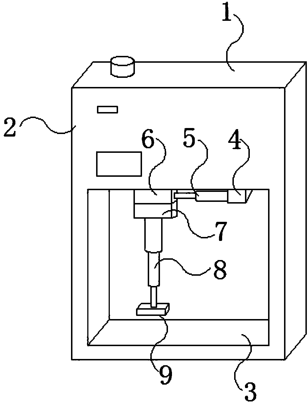
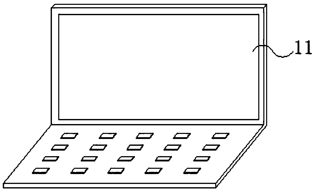
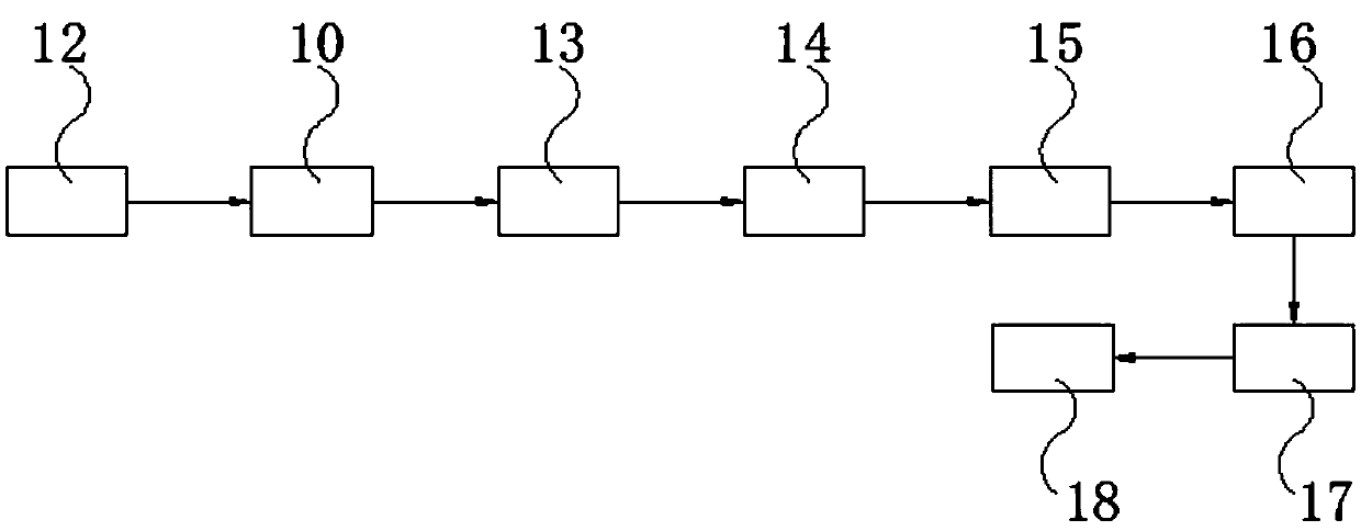
[0018] See Figure 1-4 , The present invention provides a technical solution: a computer input keyboard with radio frequency fluorescence, including a housing 1, a control box 2, an experiment table 3, a first hydraulic cylinder 4, a first hydraulic rod 5, a slider 6, a second Hydraulic cylinder 7, second hydraulic rod 8, wear resistance tester 9, signal receiving module 10, computer 11, signal transmitting module 12, starting module 13, data recording module 14, data recording transmission module 15, data recording receiving module 16 , Central processing module 17 and storage module 18. The upper part of the housing 1 is provided with a control box 2, the lower part of the housing 1 is provided with a test bench 3, and the bottom of the control box 2 is provided with a first hydraulic cylinder 4 and a first hydraulic cylinder 4 The slider 6 is connected through the first hydraulic rod 5, the bottom of the slider 6 is connected with the second hydraulic cylinder 7, and the bottom of the second hydraulic cylinder 7 is connected with the wear resistance tester 9 through the second hydraulic rod 8. The control box 2 A signal receiving module 10, a start module 13, a data recording module 14 and a recording card module transmission module 15 are arranged inside. A computer 11 is arranged in the remote environment of the housing 1, and a signal transmitting module 12 is arranged inside the computer 11 to receive data recording Module 16, central processing module 17, and storage module 18.
[0019] Further, the casing 1 and the computer 11 are connected through a wireless network.
[0020] Further, the signal transmitting module 12 is signally connected to the signal receiving module 10, the signal receiving module 10 is electrically connected to the activation module 13, the activation module 13 is electrically connected to the data recording module 14, and the data recording module 14 is electrically connected to the data recording transmission module 15.
[0021] Further, the data recording transmission module 15 is signally connected to the data recording receiving module 16, the data recording receiving module 16 is electrically connected to the central processing module 17, and the central processing module 17 is electrically connected to the storage module 18.
[0022] Further, the starting module 13 is electrically connected to the first hydraulic cylinder 4 and the second hydraulic cylinder 7.
[0023] Further, a sliding groove is provided at the bottom of the control box 2 to facilitate the sliding of the slider 6 on the sliding groove.
[0024] Working principle: This kind of experimental device is mainly a shell 1, the upper part of the shell 1 is the control box 2, and the lower part is the experiment table 3. First, put the object to be tested on the experiment table 3, and then pass the start module inside the computer 11. 13. Drive the second hydraulic cylinder 7, stretch the first hydraulic rod 5 to make the abrasion resistance tester 9 close to the object to be tested, and then drive the second hydraulic cylinder 7 to drive the slider 6 by extending and retracting the second hydraulic rod 8. The sliding of the chute drives the abrasion resistance tester 9 to perform abrasion resistance test on the measured object. During the test, the data recording module 14 inside the control box 2 will record the abrasion resistance test data, and then pass the data After the record transmission module 15 transmits the data to the data record reception module 16 to receive the data, it transmits the data to the central processing module 17, and the central processing module 17 transmits the data to the storage module 18 for storing information.
[0025] Although the embodiments of the present invention have been shown and described, those of ordinary skill in the art can understand that various changes, modifications, and substitutions can be made to these embodiments without departing from the principle and spirit of the present invention. And variations, the scope of the present invention is defined by the appended claims and their equivalents.

PUM

no PUM

Description & Claims & Application Information

We can also present the details of the Description, Claims and Application information to help users get a comprehensive understanding of the technical details of the patent, such as background art, summary of invention, brief description of drawings, description of embodiments, and other original content. On the other hand, users can also determine the specific scope of protection of the technology through the list of claims; as well as understand the changes in the life cycle of the technology with the presentation of the patent timeline. Login to view more.

Similar technology patents

Interrupt handling method and device

ActiveCN101976206AFast executionReduced probability of interrupt lossProgram initiation/switchingOperating systemComputer science
Owner:北京中星天视科技有限公司

Method and system for BitMap Analysis System for high speed testing of memories

InactiveUS20060248414A1Low area overheadFast executionStatic storageEqual sizeTester device
Owner:STMICROELECTRONICS PVT LTD

Classification and recommendation of technical efficacy words

  • Fast execution
  • Low cost

Practical, redundant, failure-tolerant, self-reconfiguring embedded system architecture

InactiveUS7117390B1High robustness/redundancyFast executionError detection/correctionEmbedded systemSoftware modules
Owner:NAT TECH & ENG SOLUTIONS OF SANDIA LLC

Semiconductor device

InactiveUS6975142B2Low costReduce manufacturing stepsTransistorSolid-state devicesVoltage amplitudeSemiconductor
Owner:SEMICON ENERGY LAB CO LTD
Why Eureka
Try Eureka