A Large Scan Angle Array Antenna and Its Design Method

An array antenna, scanning angle technology, applied in the direction of antennas, antenna arrays, and devices for manufacturing antenna arrays, etc., can solve the problem of high grating lobes

Active Publication Date: 2021-01-05
NORTHWEST INST OF NUCLEAR TECH
View PDF10 Cites 0 Cited by
  • Summary
  • Abstract
  • Description
  • Claims
  • Application Information

AI Technical Summary

Problems solved by technology

[0004] The technical problem to be solved by the present invention is to provide a large scanning angle antenna array with achievable engineering height, so as to solve the problem of excessively high grating lobes when scanning large-scale antenna arrays with large spacing

Method used


Image

  • A Large Scan Angle Array Antenna and Its Design Method
  • A Large Scan Angle Array Antenna and Its Design Method
  • A Large Scan Angle Array Antenna and Its Design Method

Examples


Embodiment Construction

[0081] In order to make the purpose, advantages and features of the present invention clearer, a large scanning angle array antenna proposed by the present invention and its design method will be further described below in conjunction with the accompanying drawings and specific embodiments. Advantages and features of the present invention will be apparent from the following description and claims. It should be noted that: the drawings are all in a very simplified form and use inaccurate proportions, which are only used to facilitate and clearly illustrate the purpose of the embodiments of the present invention; secondly, the structures shown in the drawings are often actual structures part; again, each drawing needs to display different emphasis points, and sometimes adopts different scales.

[0082] The present invention is described based on the accompanying drawings and the following embodiments.

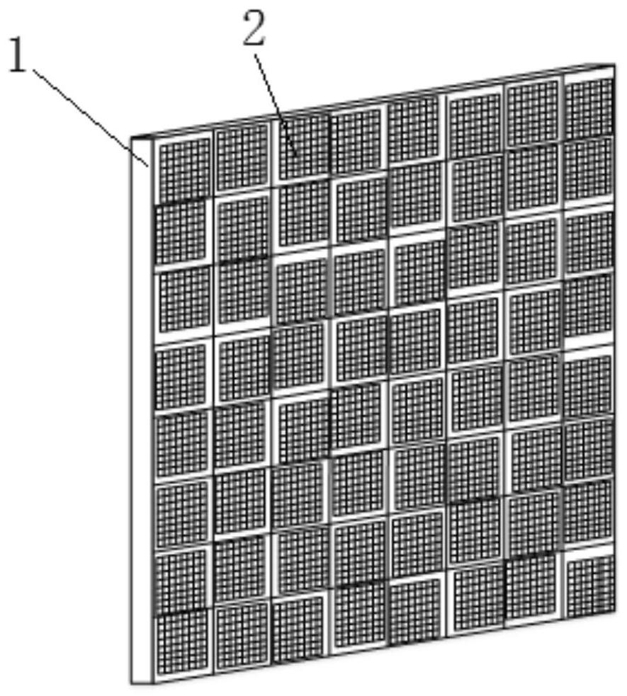
[0083] A large scan angle array antenna, such as figure 1 As shown, includ...


PUM


Abstract

A large-scanning-angle array antenna and a design method thereof are provided. Scanning of an azimuth and a pitching + / - 45-degree scanning angle can be realized under a TR assembly interval close toone wavelength, and the maximum grating lobe of a visual space is -20dB lower than a main lobe. The antenna comprises a frame and an antenna subarray. N*M areas are arranged in the frame, and each area is provided with an antenna subarray; each antenna subarray comprises a TR assembly sub-array, a sub-array feed adapter plate and a sub-array antenna plate. The input end of the sub-array feed adapter plate is connected with the TR assembly sub-array, the output end of the sub-array feed adapter plate is connected with the input end of the sub-array antenna plate, and the sub-array antenna platetakes the antenna unit group as the output. Through the subarray feed adapter plate, the distance between subarray antenna units is reduced, the reduced subarray antenna offsets in the subarray sizeof the original TR assembly, and through the structure, grating lobes are inhibited, and the engineering level is improved.

Description

technical field [0001] The invention relates to an antenna structure, in particular to a large scanning angle array antenna and a design method thereof. Background technique [0002] Phased array antennas are widely used in the fields of radar guidance and wireless communication because of their advantages such as fast beam scanning, flexible beam forming, and high reliability. There are various structural forms of array antennas. The most basic form is a linear array, which refers to an array antenna in which the centers of multiple radiating elements are on a straight line. The element spacing can be equal or unequal. When the centers of the antenna's radiating elements are arranged on a plane, it is called a plane array. The contour shape formed around the area array can be a rectangular area array or a circular area array. In the array antenna, the element spacing is generally 1 / 2 wavelength. If the element spacing is too large, unnecessary grating lobes will be formed...

Claims


Application Information

Patent Timeline
Patent Type & Authority Patents(China)
IPC IPC(8): H01Q21/29H01Q21/00H01Q1/50
CPCH01Q1/50H01Q21/0006H01Q21/0087H01Q21/293
Inventor 谢少毅李佳伟邵浩郭乐田邓广健黄文华张余川
Owner NORTHWEST INST OF NUCLEAR TECH
Why Eureka
Try Eureka