Two-dimensional circularly polarized wide-angle scanning phased array antenna

A phased array antenna and wide-angle scanning technology, which is applied in the direction of antenna, antenna array, antenna grounding switch structure connection, etc., can solve the problem that the scanning angle has not been well expanded, the scanning beam axial ratio is not ideal, and the circular pole Minimize the narrow working bandwidth of the phased array, achieve good circular polarization scanning characteristics, optimize antenna parameter configuration, and increase the effect of equivalent path length

Active Publication Date: 2022-05-17
10TH RES INST OF CETC
View PDF0 Cites 0 Cited by
  • Summary
  • Abstract
  • Description
  • Claims
  • Application Information

AI Technical Summary

Problems solved by technology

Although this patent application has achieved circular polarization scanning, the scanning angle has not been well expanded, and the scanning area is not continuous. ° Azimuth presentation of
In addition, the circularly polarized phased array demonstrated by this scheme has a narrow operating bandwidth and the axial ratio performance of the scanning beam is not ideal

Method used


Image

  • Two-dimensional circularly polarized wide-angle scanning phased array antenna
  • Two-dimensional circularly polarized wide-angle scanning phased array antenna
  • Two-dimensional circularly polarized wide-angle scanning phased array antenna

Examples


Embodiment Construction

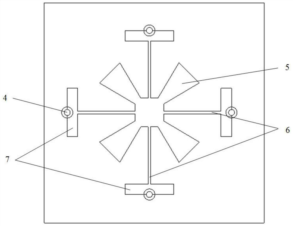
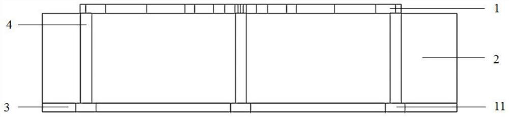
[0021] refer to Figure 1-Figure 3 . In the preferred embodiment described below, a two-dimensional circularly polarized wide-angle scanning phased array antenna includes: the antenna radiation patch 1 fixed on the upper surface of the antenna dielectric layer 2, the metal layer on the lower surface of the antenna dielectric layer 2 The wide-beam circularly polarized wide-angle phased array antenna unit composed of the floor 3 and the antenna feeding probe 4, wherein: the antenna radiation patch 1 is connected to the rectangular parasitic patch with a high-impedance matching microstrip line 6 with a cross in the center and equal length Sheet 7 performs impedance matching on the antenna, and a windmill-shaped microstrip radiation patch 5 is formed on the symmetrical center of the diagonal bisector of the corner of the antenna radiation patch 1 to excite equal-amplitude in-phase polarization orthogonal degenerate modes; The needle 4 passes through the antenna dielectric layer 2...


PUM


Abstract

The invention discloses a two-dimensional millimeter-wave circularly polarized wide-angle scanning phased array antenna, which relates to the technical field of millimeter-wave antennas. The present invention is realized through the following technical solutions: the antenna radiation patch is connected to the rectangular parasitic patch with a high-impedance matching microstrip line with a cross carved in the center to perform impedance matching on the antenna, and the diagonal bisector at the corner of the antenna radiation patch On the center of symmetry, a pinwheel-shaped microstrip radiation patch is fabricated to excite the degenerate mode of equal-amplitude in-phase polarization and orthogonality. The feeding probe passes through the antenna dielectric layer and connects the antenna radiation patch through four rectangular parasitic patches. Each Antenna unit four feed probes 4 through the same amplitude sequentially with a difference of 90 ° The rotating feeding structure is used for feeding, and the windmill-shaped microstrip radiation patch is connected to the four rectangular parasitic patch rectangular blocks of the four metallized probes for feeding, and the feeding phases are respectively 90 degrees apart. ° The equal-amplitude excitation forms circularly polarized radiation, and the antenna array is arranged in a rectangular array with equal spacing between units to form an antenna array front.

Description

technical field [0001] The invention belongs to the technical field of microwave antennas, in particular to a two-dimensional millimeter-wave circularly polarized wide-angle scanning antenna array. Background technique [0002] With the development of modern aerospace technology, the requirements for various radar phased array antennas are increasing. Compared with the traditional mechanical scanning radar system, the phased array antenna has more convenient beam control, more sensitive and convenient beam response, and can realize high-speed and high-performance beam scanning and beam tracking. At the same time, the phased array antenna has the advantages of light weight, low profile and small installed volume, so it has received more and more attention. However, the planar phased array antenna is severely limited by the narrow beam scanning range. As the antenna array scanning angle increases in the elevation plane, the antenna scanning gain will decrease severely, and ef...

Claims


Application Information

Patent Timeline
Patent Type & Authority Patents(China)
IPC IPC(8): H01Q3/34H01Q1/36H01Q1/38H01Q1/50H01Q21/00
CPCH01Q3/34H01Q1/50H01Q1/36H01Q1/38H01Q21/00
Inventor 王多何海丹谢玲
Owner 10TH RES INST OF CETC
Why Eureka
Try Eureka