
Protective component, assembly jig, and electronic device assembly method

A technology for electronic equipment and assembling fixtures, applied in metal processing equipment, manufacturing tools, metal processing and other directions, can solve problems such as increasing production costs, reducing production efficiency, and failing to prevent paint peeling well, avoiding scratches and solving problems. paint peeling effect

Active Publication Date: 2020-09-04
OPPO CHONGQING INTELLIGENT TECH CO LTD
View PDF5 Cites 0 Cited by
  • Summary
  • Abstract
  • Description
  • Claims
  • Application Information

AI Technical Summary

Problems solved by technology

For those that cannot be repaired by touch-up paint, only the middle frame can be scrapped
This greatly reduces production efficiency and increases production costs
And this measure is mainly to make up for it, but it does not prevent the paint from falling well.

Method used


Image

  • Protective component, assembly jig, and electronic device assembly method
  • Protective component, assembly jig, and electronic device assembly method
  • Protective component, assembly jig, and electronic device assembly method

Examples


Embodiment Construction

[0026] The present invention will be further described in detail below with reference to the drawings and embodiments. It is particularly pointed out that the following examples are only used to illustrate the present invention, but do not limit the scope of the present invention. Similarly, the following embodiments are only part of the embodiments of the present invention, but not all of them. All other embodiments obtained by those of ordinary skill in the art without creative work shall fall within the protection scope of the present invention.

[0027] Reference to "embodiments" herein means that specific features, structures, or characteristics described in conjunction with the embodiments may be included in at least one embodiment of the present invention. The appearance of the phrase in various places in the specification does not necessarily refer to the same embodiment, nor is it an independent or alternative embodiment mutually exclusive with other embodiments. Those ...


PUM


Abstract

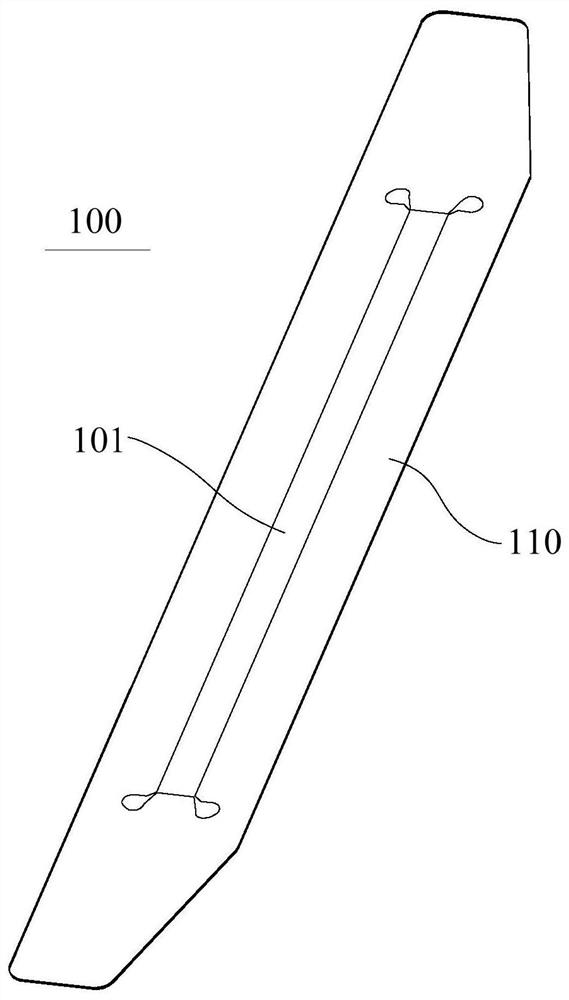
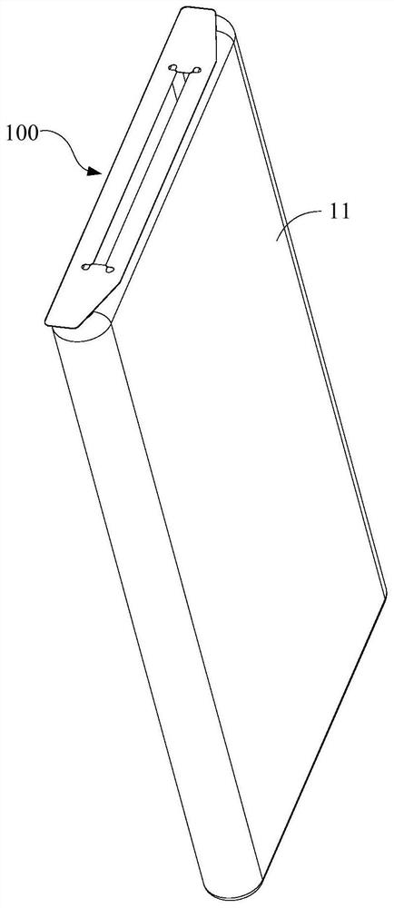
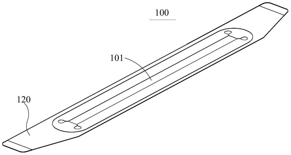
The application provides a protection assembly, an assembly jig and an electronic equipment assembly method. The protection assembly is used for protecting the appearance surface of a shell, and comprises an anti-wear sheet and a first adhesive layer which are stacked; an assembly gap is formed in the anti-wear sheet, the first adhesive layer is used for adhering the anti-wear sheet to the surfaceof the shell, and the assembly gap is arranged corresponding to an assembly hole of the shell. According to the protection assembly, the assembly jig and the electronic equipment assembly method provided by the embodiment, the protection assembly is adhered to the circumference of the assembly hole of the shell, so that the shell can be prevented from being scratched in the assembly process, andthe problem of paint falling or scratch caused by assembly of the shell is solved.

Description

Technical field [0001] The invention relates to the technical field of an auxiliary jig for assembling an electronic device, in particular to a protective component, an assembling jig and a method for assembling an electronic device. Background technique [0002] At present, in order to achieve full screen (or high screen-to-body ratio), mobile phones and other electronic devices have explored various front camera layout schemes. Among them, the use of a lifting mechanism to hide the front camera in the mobile phone shell can solve the problem of notch screen and water drop screen. And the problem that the digging screen takes up the screen space, so as to realize the "true full screen". The lifting module (hereinafter referred to as the small middle frame) usually needs to be manually installed in the large and middle frame from the outside of the installation hole of the large and middle frame (the side frame of the mobile phone), and due to inaccurate manual alignment, it will...

Claims


Application Information

Patent Timeline
Patent Type & Authority Patents(China)
IPC IPC(8): B23P19/00
CPCB23P19/00
Inventor 付鹏
Owner OPPO CHONGQING INTELLIGENT TECH CO LTD
Learn More