
Drinks filling device

A filling device, wine technology, applied in the safety device, packaging, bottle filling and other directions of the filling device, can solve the problems of high cost, easy damage and complex structure of the solenoid valve

Active Publication Date: 2019-11-26
湖南省鼎谷一酒业有限公司
View PDF6 Cites 4 Cited by
  • Summary
  • Abstract
  • Description
  • Claims
  • Application Information

AI Technical Summary

Problems solved by technology

The existing filling equipment usually uses the cooperation of solenoid valve and flow meter to control the content of filling, and the structure is complicated, especially the cost of solenoid valve is high and it is easy to damage

Method used


Image

  • Drinks filling device
  • Drinks filling device
  • Drinks filling device

Examples


Embodiment 1

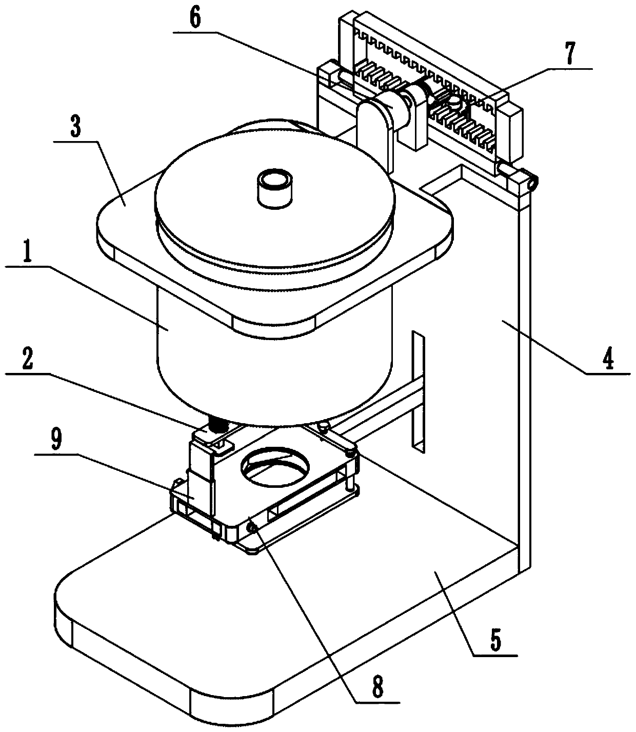
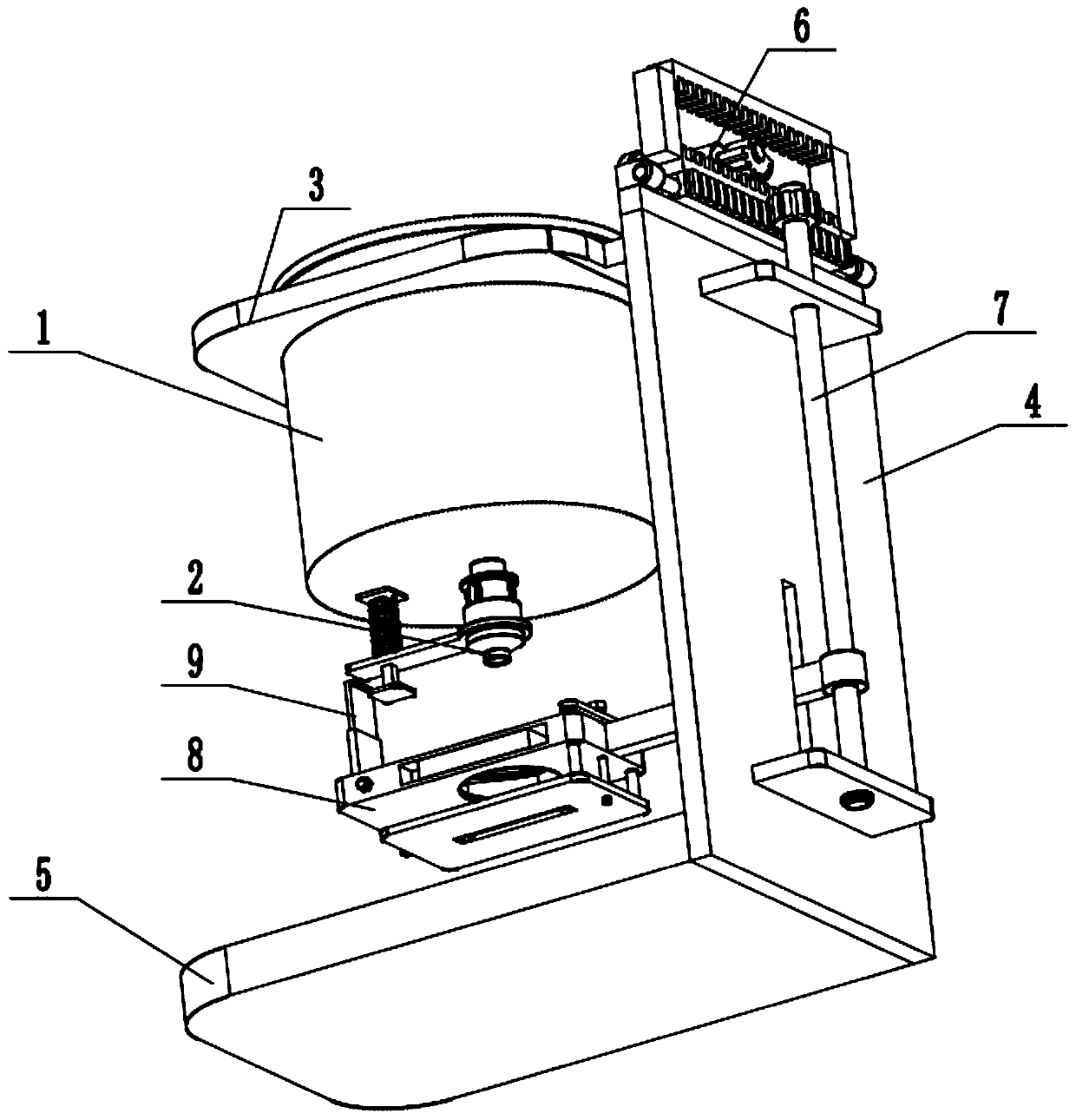
[0033] Such as Figure 1-13As shown, a wine filling device includes a wine storage barrel 1, a filling head 2, a barrel fixing seat 3, a stand 4, a base 5, a filling control mechanism 6, a lifting mechanism 7, a wine bottle seat 8 and a top pressure plate 9. The lower end of the wine storage barrel 1 is fixedly connected with the filling head 2; the wine storage barrel 1 is fixed on the barrel fixing seat 3; the barrel fixing seat 3 is fixed on the stand 4; the stand 4 fixed on the base 5; the filling control mechanism 6 is fixed on the bucket fixing seat 3; the filling control mechanism 6 is connected to the lifting mechanism 7; the lifting mechanism 7 is connected to the stand 4; the lifting mechanism 7 is connected to the wine bottle seat 8 by transmission; the wine bottle seat 8 is slidingly fitted on the stand 4; the top pressure plate 9 is fixedly connected to the wine bottle seat 8; the top pressure plate 9 is connected to the filling head 2 by transmission. A wine fil...

Embodiment 2

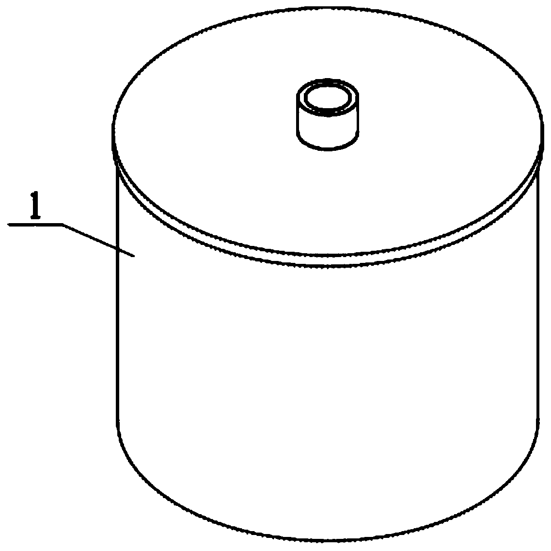
[0035] Such as Figure 1-13 As shown, the upper end of the wine storage barrel 1 is fixedly connected with a bung; the bung is provided with a wine inlet pipe with a control valve. The setting of the wine inlet pipe is used to load wine, and the wine can be stored through the wine storage barrel 1 .

Embodiment 3

[0037] Such as Figure 1-13 As shown, the filling head 2 includes a flow tube 201 with a closed bottom, a stepped flow control tube 202, a filling tube 203, a movable platen 204, a compression spring 205, a rectangular slide bar 206 and a slide bar seat 207; the flow tube The upper end of 201 is fixedly connected with the wine storage barrel 1; the lower end of the circulation pipe 201 is in sealing and sliding fit with the upper end of the stepped flow control pipe 202; the lower end of the stepped flow control pipe 202 is fixedly connected with the filling pipe 203 The lower end of the pipe body of the flow pipe 201 is evenly surrounded by a plurality of flow holes; one end of the movable platen 204 is fixed on the stepped flow control pipe 202, and the other end of the movable platen 204 is slidably fitted on the rectangular slide bar 206; The upper and lower ends of the rectangular slide bar 206 are respectively fixedly connected with a slide bar seat 207, and the slide ba...


PUM


Abstract

The invention relates to the field of drinks processing, in particular to a drinks filling device. The drinks drilling device comprises a wine storage barrel, a filling head, a barrel fixing base, a stand frame, a base, a filling control mechanism, a lifting mechanism, a wine bottle base and an ejecting plate; the lower end of the wine storage barrel is fixedly connected with the filling head; thewine storage barrel is fixed on the barrel fixing base; the barrel fixing base is fixed on the stand frame; the stand frame is fixed on the base; the filling control mechanism is fixed on the barrelfixing base; the filling control mechanism is in transmission connection with the lifting mechanism; the lifting mechanism is connected to the stand frame, and is in transmission connection with the wine bottle base; the wine bottle base is slidingly matched on the stand frame; and the ejecting plate is fixedly connected to the wine bottle base, and is in transmission connection with the filling head. The drinks filling device can fix wine bottles with different sizes in the drinks production process for quantitative filling.

Description

technical field [0001] The invention relates to the field of wine processing, in particular to a wine filling device. Background technique [0002] In the process of wine production and filling, it is necessary to control the wine content of each bottle of wine and control the wine content within a reasonable error range. The existing filling equipment usually uses the cooperation of electromagnetic valve and flow meter to control the content during filling, and the structure is complicated, especially the electromagnetic valve is expensive and easy to damage. Contents of the invention [0003] In view of this, the present invention provides a wine filling device, which can fix wine bottles of different sizes and quantitatively fill them during the wine production process. [0004] In order to achieve the above purpose, the proposed scheme is as follows: [0005] A wine filling device, comprising a wine storage barrel, a filling head, a barrel fixing seat, a stand, a bas...

Claims


Application Information

Patent Timeline
Patent Type & Authority Applications(China)
IPC IPC(8): B67C3/24B67C3/26B67C3/20B67C3/00B67C3/28
CPCB67C3/007B67C3/20B67C3/24B67C3/26B67C3/286
Inventor 姜秀花
Owner 湖南省鼎谷一酒业有限公司
Learn More