Flue-gas treatment device

A technology of flue gas treatment and flue gas, which is applied in the direction of gas treatment, dispersed particle separation, membrane technology, etc., can solve the problems of poor flue gas denitrification effect, high nitrogen oxide content, and failure to meet national standards, etc., and achieve desulfurization and denitrification effects Good, good effect, the effect of improving grinding efficiency

Pending Publication Date: 2018-03-30
山东义丰环保机械股份有限公司
View PDF3 Cites 3 Cited by
  • Summary
  • Abstract
  • Description
  • Claims
  • Application Information

AI Technical Summary

Problems solved by technology

In the technical solution disclosed in the above documents, the removal of nitrogen oxides in the flue gas needs to ensure that the temperature of the flue gas is above 200°C, and the required removal effect of nitrogen oxides has been achieved. Since the flue gas needs to be desulfurized before denitrification, after desulfurization The temperature of the flue gas is usually difficult to maintain above 200°C, which leads to poor denitrification effect of the flue gas, and the content of nitrogen oxides in the flue gas after treatment is high, which cannot meet the national standard

Method used


Image

  • Flue-gas treatment device
  • Flue-gas treatment device
  • Flue-gas treatment device

Examples


Embodiment 1

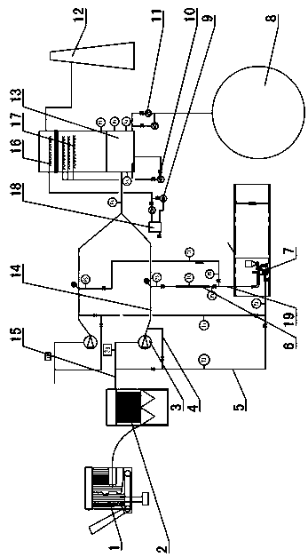
[0042] Such as figure 1 As shown: the flue gas treatment device also includes a dust collector 2, the intake end of the dust collector 2 is connected with the smoke outlet of the boiler 1, and the flue gas of the boiler 1 first enters the dust collector 2 to remove dust and then enters the main flue 14 , so as to prevent the smoke from affecting the mixing of the sodium bicarbonate powder and the flue gas, and also prevent the smoke from affecting the reaction of the sodium bicarbonate powder and the sulfur oxides and nitrogen oxides in the flue gas. The dust collector 2 can be a bag dust collector, an electric dust collector or a tubular dust collector, etc.

[0043] The gas outlet end of the dust collector 2 is communicated with the intake end of the main flue 14 through the flue gas input channel 15, and the output end of the main flue 14 is connected with the dust removal module. In the present embodiment, the dust removal module is a washing tower 13, and the main flue T...

Embodiment 2

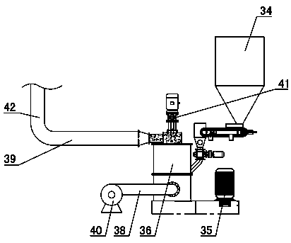
[0084] Such as Figure 6~7 Shown: the difference between embodiment 2 and embodiment 1 is: the grinding device is arranged between the powder delivery pipe 39 and the grinding device smoke outlet pipe 42, and the transportation of sodium bicarbonate powder is realized by means of negative pressure transportation. The smoke inlet pipe 38 of the grinding device is arranged at intervals on the lower side of the powder conveying pipe 39, and a balance pipe 37 is arranged between the smoke inlet pipe 38 of the grinding device and the powder conveying pipe 39, and the balance pipe 37 is vertically arranged, and the balance pipe 37 The upper end communicates with the middle part of the powder conveying pipe 39, and the lower end of the balance pipe 37 communicates with the smoke inlet pipe 38 of the grinding device, so that the pressure of the smoke inlet pipe 38 of the grinding device and the powder conveying pipe 39 can be balanced to ensure that the flue gas and sodium bicarbonate ...


PUM


Abstract

A flue gas treatment device belongs to the technical field of environmental protection equipment. It is characterized in that it includes a main flue (14), a sodium bicarbonate grinding device (7), a powder preheating module (6) and a dust removal module. Input, the outlet end of the main flue (14) is connected with the inlet end of the dust removal module, the inlet end of the sodium bicarbonate grinding device (7) is connected with the inlet end of the main flue (14), and the sodium bicarbonate grinding device The gas outlet of (7) is connected to the main flue (14), the powder preheating module (6) is set between the sodium bicarbonate grinding device (7) and the main flue (14), and the dust removal module is a wet desulfurization tower or scrubber (13). The flue gas treatment device fully reacts the sodium bicarbonate powder with flue gas, reduces the energy consumption of the powder preheating module, has good desulfurization and denitrification effects, and can directly treat low-temperature flue gas.

Description

technical field [0001] A flue gas treatment device belongs to the technical field of environmental protection equipment. Background technique [0002] Modern environmental science warns us that atmospheric environmental resources are not endless, just like water resources and mineral resources, it is a wealth shared by human beings and must be protected from generation to generation, highly cherished and rationally utilized. Smoke is a mixture of gas and smoke and is the main cause of air pollution in residential areas. The composition of the flue gas is very complex. The gas includes water vapor, sulfur dioxide, nitrogen, oxygen, carbon monoxide, carbon dioxide, hydrocarbons, and nitrogen oxides. The smoke includes fuel ash, coal particles, oil droplets, and pyrolysis products. Therefore, The pollution of flue gas to the environment is the compound pollution of various poisons. At present, the treatment of flue gas generally includes three parts: dust removal, desulfuriza...

Claims


Application Information

Patent Timeline
Patent Type & Authority Applications(China)
IPC IPC(8): B01D53/83B01D53/60
CPCB01D53/83B01D53/60B01D2258/0283
Inventor 魏向海车秀花赵肖飞刘延钊
Owner 山东义丰环保机械股份有限公司
Why Eureka
Try Eureka