Multifunctional working trolley for tunnel
A multi-functional, workbench technology, applied in tunnels, mining equipment, earth-moving drilling, etc., can solve problems such as difficulty in single operation or parallel operation, difficulty in cooperating operation of working arms, and increased difficulty in workpiece calibration. The equipment cost is low, the overall reliability is improved, and the adjustment accuracy is good.
- Summary
- Abstract
- Description
- Claims
- Application Information
AI Technical Summary
Problems solved by technology
Method used
Image
Examples
Embodiment 1
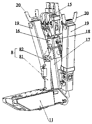
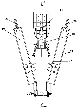
[0041] see Figure 1 to Figure 8 As shown, the tunnel multifunctional operation trolley of the present invention includes a vehicle body 1 , a main working arm 2 , a first side working arm 3 and a second side working arm 4 .
[0042] The vehicle body 1 is used as an assembly carrier part of the component parts of the trolley, that is to say, the vehicle body 1 can be understood as an installation carrier of each component, and can be used for installation and layout of each component.
[0043] The main working arm 2, the first side working arm 3 and the second side working arm 4 are assembled on the vehicle body 1 and can implement independent operation and parallel operation, while the first side working arm 3 and the second side working arm 4 are separated on both sides of the main working arm 2. It can be understood that the main working arm 2, the first side working arm 3 and the second side working arm 4 can work independently, and can also work in parallel, that is, coo...
Embodiment 2
[0052] see Figure 1 to Figure 8 As shown, the tunnel multifunctional operation trolley of the present invention includes a vehicle body 1 , a main working arm 2 , a first side working arm 3 and a second side working arm 4 . The vehicle body 1 is used as an assembly carrier part of the component parts of the trolley.
[0053] The main working arm 2, the first side working arm 3 and the second side working arm 4 are assembled on the vehicle body 1 and can implement independent operation and parallel operation, while the first side working arm 3 and the second side working arm 4 are separated on both sides of the main working arm 2.
[0054] The front end of the main working arm 2 is hinged to the main manipulator 5 , the front end of the first side working arm 3 is hinged to the first side manipulator 6 , and the front end of the second side working arm 4 is hinged to the second side manipulator 7 .
[0055] The main manipulator 5, the first side manipulator 6, and the second...
Embodiment 3
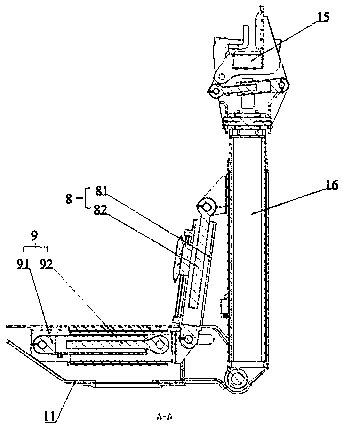
[0074] The basic structure and the structure of each working arm are the same as those of the second embodiment, the difference is that the second telescopic rod 92 is fixedly connected with the first cylinder 81 . Fixed connection refers to the structure that can be fixedly connected with the second telescopic rod 92 and the first cylinder 81, that is, the fixed connection is realized when the first driving member 8 and the second driving member 9 operate part of the time, that is, the first driving The angle between the second driving member 8 and the second driving member 9 is constant. When adjusting the operation of the corresponding manipulator, the first driving member 8 and the second driving member 9 must run at the same time. The first driving member is adjusted along the rotation direction of the manipulator through the second driving member 9. 8 position, that is, the swing speed can be accelerated to realize fast swing, or the position of the first drive member 8 c...
PUM
 Abstract
Description
Claims
Application Information
 - R&D
- Intellectual Property
- Life Sciences
- Materials
- Tech Scout
- Unparalleled Data Quality
- Higher Quality Content
- 60% Fewer Hallucinations
Browse by: Latest US Patents, China's latest patents, Technical Efficacy Thesaurus, Application Domain, Technology Topic, Popular Technical Reports.
© 2025 PatSnap. All rights reserved.Legal|Privacy policy|Modern Slavery Act Transparency Statement|Sitemap|About US| Contact US: help@patsnap.com


