Permanently-tight interlocked non-return nut

A nut and locking technology, applied in the direction of nuts, screws, bolts, etc., can solve the problems of impossibility and repeated use, and achieve the effect of reliable performance, wide application and simple structure

Pending Publication Date: 2019-11-26
韩树海
View PDF0 Cites 5 Cited by
  • Summary
  • Abstract
  • Description
  • Claims
  • Application Information

AI Technical Summary

Problems solved by technology

But none of these can meet the needs of particularly important connection occasions, nor can it be reused and n

Method used


Image

  • Permanently-tight interlocked non-return nut
  • Permanently-tight interlocked non-return nut
  • Permanently-tight interlocked non-return nut

Examples


Embodiment 1

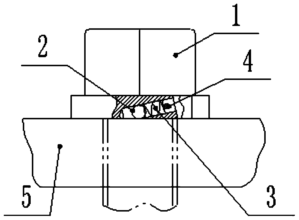
[0022] This embodiment is a plane interlocking non-return nut, such as figure 1 and 2 As shown: a spring hole is obliquely opened on the upper end surface of the lower end of the nut 1. The spring hole is an oblique hole. The oblique hole is perpendicular to the diameter. The apex of the oblique angle is the direction of rotation of the nut; the rolling body 2 and spring 3 are placed in the spring hole, the spring 3 is a compressed spring, the rolling body part protrudes from the lower end surface of the nut, and the upper end of the spring hole is provided with a lock pin hole, which is inserted Self-locking locking pin 4, rolling body is connected with locking pin by spring.

[0023] According to torque requirements, the number of spring holes on the nut is generally 1-12.

[0024] When working, when the nut 1 is screwed to the plane contact with the fastened part 5, the rolling body 2 is squeezed to overcome the elastic force of the spring 3, and shrinks to the lower end ...

Embodiment 2

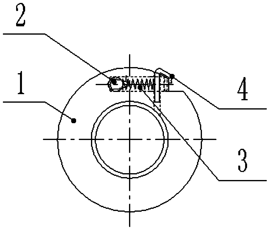
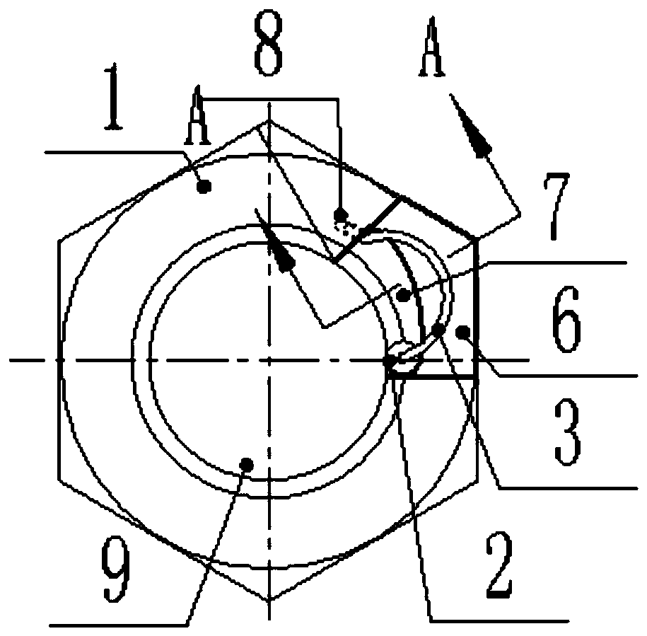
[0026] This embodiment is a rotation interlocking non-return nut, such as image 3 and 4 As shown: there is a spring groove 6 on the upper surface of the nut 1, and the special-shaped groove 7 is a groove opened on the inner edge of the nut below the spring groove. The friction angle of the nut is the rotation direction of the nut relative to the small end; a spring socket 8 is set at one end of the spring groove 6, and a spring 3 is placed in the spring groove, and the spring 3 adopts an arc-shaped special-shaped spring; One end of the spring 3 is inserted into the central hole of the rolling body, and the other end is inserted into the spring socket 8, the rolling body remains against the relatively small end of the special-shaped groove 7, and the upper end of the spring groove 6 is covered with a cover.

[0027] According to torque requirements, the number of spring grooves and special-shaped grooves on the nut is generally 1-12.

[0028] The sealing of the end surface (...


PUM


Abstract

The invention belongs to the mechanical field, and particularly relates to an anti-loosing nut. A permanently-tight interlocked non-return nut is a planar interlocked non-return nut; a spring hole isformed slantwise from the lower end surface to the upper end surface of the nut; a rolling body and a spring are placed in the spring hole; the rolling body is partially bulged out of the lower end surface of the nut; a lock pin hole is formed in an upper-end hole opening of the spring hole, and a self-locking lock pin is inserted; and the rolling body is connected with the lock pin through the spring. The permanently-tight interlocked non-return nut adopts a creative and new anti-loosing manner, and is simple in structure. An anti-loosing torque is measurable and controllable, and a pluralityof interlocking mechanisms are installed on the nut, and can be controlled as needed. The permanently-tight interlocked non-return nut is permanently-tight, reliable in performance, and wide in application; the permanently-tight interlocked non-return nut can be repeatedly used for unlimited times in the own limit service life; and the permanently-tight interlocked non-return nut is applicable tovarious fields or equipment needing high strength, for example, various vehicles, railway tracks, strictly-sealed chemical equipment, nuclear facilities and the like, and completely capable of replacing and superior to imported nuts in important occasions such as high-speed railways.

Description

technical field [0001] The invention belongs to the field of machinery, in particular to anti-loosening bolts and nuts. Background technique [0002] There are three commonly used anti-loosening methods for existing nuts: frictional anti-loosening, mechanical anti-loosening and permanent anti-loosening. Mechanical anti-loosening and friction anti-loosening are called detachable anti-loosening, while permanent anti-loosening is called non-removable anti-loosening. Commonly used permanent anti-loosening methods include: spot welding, riveting, bonding, etc. This method mostly destroys the threaded fasteners during disassembly and cannot be reused. Common friction and anti-loosening methods include: using gaskets, self-locking nuts and double nuts. Common mechanical anti-loosening methods: use cotter pins, stop washers and string wire ropes, etc. However, these cannot meet the needs of particularly important connection occasions, nor can they be reusable and never loose. F...

Claims


Application Information

Patent Timeline
IPC IPC(8): F16B39/22F16B37/04
CPCF16B37/042F16B39/22
Inventor 韩树海
Owner 韩树海
Why Eureka
Try Eureka